
Motor and belt speed
With power disconnected, belt placement selects spindle speed from the model's chart. Close the cover before restarting; choose speed for bit diameter and wood rather than treating one speed as universal.
Understand the quill, belt speeds, table and workholding behind repeatable square holes.
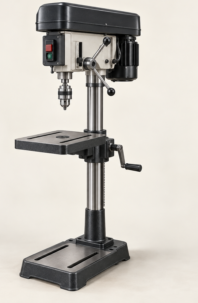
An original educational poster groups twelve model-grounded parts and systems. The numbered descriptions remain readable below the artwork on narrow screens.
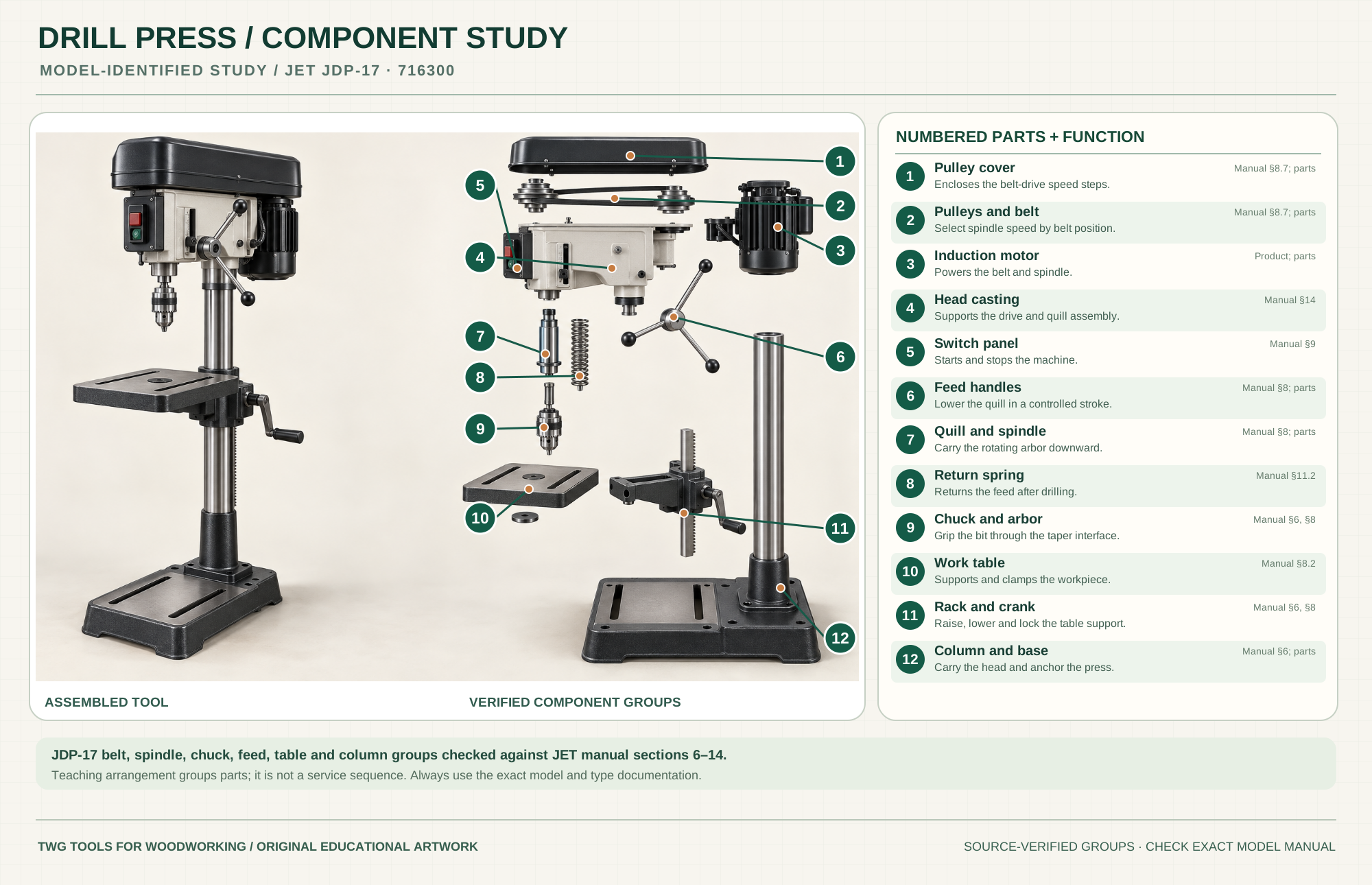
Encloses the belt-drive speed steps.
Manual §8.7; partsSelect spindle speed by belt position.
Manual §8.7; partsPowers the belt and spindle.
Product; partsSupports the drive and quill assembly.
Manual §14Starts and stops the machine.
Manual §9Lower the quill in a controlled stroke.
Manual §8; partsCarry the rotating arbor downward.
Manual §8; partsReturns the feed after drilling.
Manual §11.2Grip the bit through the taper interface.
Manual §6, §8Supports and clamps the workpiece.
Manual §8.2Raise, lower and lock the table support.
Manual §6, §8Carry the head and anchor the press.
Manual §6; partsTechnical references: JET JDP-17 operating and parts manual · JET JDP-17 official model page. Original educational artwork depicts verified component groups and their relationships; it is not a service sequence or a replacement for the exact model manual.
A drill press brings a rotating bit down through a fixed vertical path into clamped stock. The JET JDP-17 reference is a floor machine with a belt-and-pulley speed system, a depth stop, a rack-raised table and a 5/8-inch chuck. A handheld drill reaches assembled work, but depends more on the operator or a jig for angle and repeated depth. A press is limited by its throat, quill travel and table clearance.
An induction motor drives the spindle by belt and pulleys inside the closed upper cover. Feed handles lower the quill and spindle; a return spring brings them back. The chuck and arbor hold the bit. The table, column and base provide a rigid reference. The poster separates documented groups to teach function, not a service or assembly sequence.
With power disconnected, belt placement selects spindle speed from the model's chart. Close the cover before restarting; choose speed for bit diameter and wood rather than treating one speed as universal.
The quill moves vertically while the spindle rotates inside it. The taper-held arbor and keyed chuck grip a suitable bit; remove the chuck key before power is restored.
Feed handles control descent; the depth stop limits a repeated stroke. Confirm the stop against scrap, especially with a pointed bit or a sacrificial backer.
The table raises on the column rack, rotates and tilts for work access. Lock all adjustments and verify squareness before a precision hole.
The cast base supports the column and machine head. Secure the press and keep its center of mass stable; long stock needs separate support.
Know the stop switch location and check that the quill returns without binding. Faulty return, chuck retention or unusual vibration calls for service.
These decisions make the mechanism useful at the bench.
Read the JDP-17 speed chart, bit instructions and wood condition. Disconnect power before moving belts; tension and close the pulley cover as directed.
Clamp the blank or use a drill-press vise anchored to the table. Round, narrow or small pieces can spin violently if held by hand.
Mark the center, select a bit, set a backer and dry-run the stroke. Use the depth stop for repeat holes and clear chips during deep cuts.
A fence, stop block and clamped stock place repeated shelf-pin, handle or hinge holes consistently.
A properly sized Forstner bit makes controlled recesses; use light feed and clear chips before heat builds.
Use a fence or jig to keep a row of dowel or mortise-waste holes aligned, then finish fit with the appropriate tool.
Use the steps for a first pass, then inspect the work before changing the setup.
A brad-point spur helps a hole start at a mark. A fence and stop can make location more repeatable than aiming at each mark alone.
Larger bits often need lower speed and greater chip clearance. Follow the bit maker and JET chart instead of extrapolating from small twist bits.
A backer supports the wood fibers at breakthrough. Verify its placement and clamp it with the work.
A slipping or wobbling chuck may indicate a dirty or improperly seated taper. Follow the model manual's correction, never grip a turning chuck.
Floor presses offer more table-to-chuck clearance; benchtop machines trade capacity for footprint.
JDP-17 uses a belt arrangement. Other machines change speed by mechanical or electronic controls; the speed and service instructions differ.
Swing limits how far a hole can be from a board edge. Quill travel limits uninterrupted depth; neither alone describes usable clearance.
Chuck capacity and spindle taper are separate specifications. Match the bit shank to the chuck and use only approved tooling.
Stop the tool and disconnect power before investigating a fault or changing a part.
Check bit sharpness, center mark, table/fence registration, work clamping and feed pressure.
Check speed, bit condition, chip clearance, belt tension and clamping; stop if vibration persists.
Check stop lock, table lock and backer compression; confirm on scrap.
Use the exact tool manual for setup, limits and replacement parts. These lessons, documents and model pages teach relevant techniques or help compare real variations.
These maker-owned links document relevant tools and tool brands. A product brand may use another company's factory; compare the exact model before choosing parts or accessories.
Cutters, abrasives, guards, guides, dust fittings and service parts vary by tool. Check the model plate and manufacturer manual before ordering or changing a component.
Compare the Drilling family →Continue through the Tools library