
Palm grip and switch
The upper grip keeps hand pressure centered while the switch or speed dial stays reachable without shifting the pad off the work.
Learn how a random-orbital sander moves, how the pad stack carries the abrasive, why hole alignment changes dust pickup, and how grit choices affect the surface under finish.
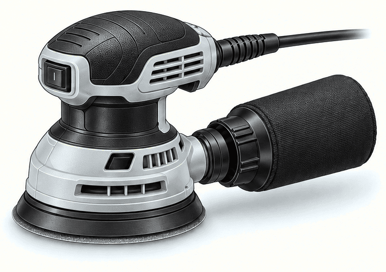
A substantial exploded study maps twelve parts and systems to their functions. The drawings use model-specific manufacturer sources, and the parts list remains readable below the artwork on small screens.
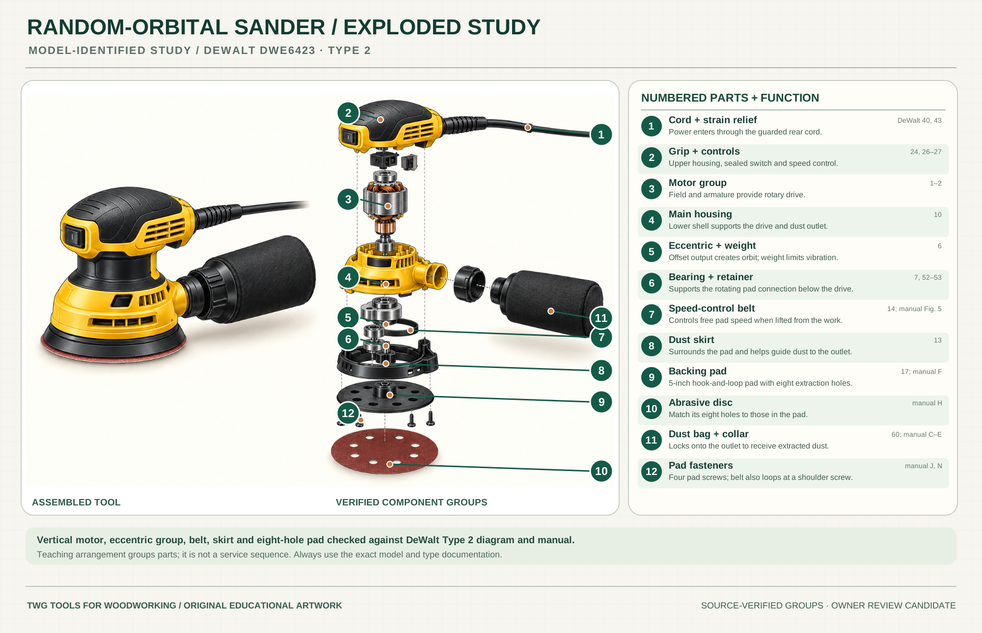
Carry power through the guarded rear entry.
Parts 40, 43Upper housing provides the hand grip, protected switch and speed setting.
Parts 24, 26–27Field and armature generate rotary drive on the vertical axis.
Parts 1–2Encloses the drive and carries the dust outlet.
Part 10The offset output creates orbit; the separate weight limits vibration.
Part 6; product overviewSupport the pad connection below the motor drive.
Parts 7, 52–53Limits free pad speed when the tool is lifted from the surface.
Part 14; manual Fig. 5Surrounds the pad and helps direct dust toward the outlet.
Part 13; manual Fig. 5Holds five-inch hook-and-loop abrasive and provides eight dust holes.
Part 17; manual FIts eight holes must align with the backing pad holes.
Manual HLock to the side outlet to collect sanding dust.
Part 60; manual C–EFour screws fasten the pad; the belt loops around a shoulder screw and retainer.
Manual J, NTechnical references: DeWalt DWE6423 Type 2 official exploded diagram · DeWalt DWE6423 Type 2 instruction manual · DeWalt DWE6423 product details. Original educational artwork depicts verified component groups and their relationships; it is not a service sequence or a replacement for the exact model manual.
A random-orbit sander combines a small eccentric orbit with free pad rotation. That motion spreads scratches in changing directions. A sheet or finish sander mainly vibrates in a smaller orbit; a belt sander removes stock far more aggressively. Random orbit does not erase deep scratches automatically: grit, pressure, pad condition and inspection still control the result.
The motor drives an eccentric that moves the round backing pad in a small orbit. The pad is also free to rotate; the exact bearing, brake and counterweight arrangement varies by model. Abrasive attaches by hook-and-loop or, on some models, pressure-sensitive adhesive. Dust passes through matching holes in the disc and pad toward the tool's collection outlet.
The upper grip keeps hand pressure centered while the switch or speed dial stays reachable without shifting the pad off the work.
The motor body sits above the lower mechanism and turns the sander without making the outer shell split universal across brands.
Many electric models use an internal fan and outlet to move dust toward a bag or canister; an extractor can provide suction on compatible models. Align the abrasive and pad holes and check the exact tool's dust path.
An eccentric drive creates the small orbital movement. Bearings, pad brakes and dampers vary by model and affect startup, stop and pad behavior.
The pad supports the abrasive disc, needs a matching hole pattern, and wears out as a replaceable model-specific part.
The disc does the cutting. Grit, material, hole pattern, and dust loading decide whether the tool refines the surface or scratches it again.
These decisions make the mechanism useful at the bench.
The disc rotates freely while its center travels in a small orbit, spreading scratch direction across the surface.
Move through logical grit steps so each stage removes the scratch pattern from the prior stage.
Dust moves best when holes line up across the abrasive, pad, and collection path.
Tilting the pad at an edge removes material fast and can soften a crisp arris before the surface is ready.
Start with the least aggressive grit that removes the defect. Keep the whole pad flat and moving in overlapping passes. Check the surface with low-angle light before moving finer.
Remove dried glue and address a height mismatch before fine sanding. A finer disc will polish a ridge rather than flatten it; avoid tipping the pad onto the high spot.
Keep most of the pad supported on wide faces. Sand crisp edges, narrow rails and shaped profiles deliberately by hand or with a suitable smaller tool.
Use the steps for a first pass, then inspect the work before changing the setup.
Move to the next grit only after the deeper scratches, milling marks, or defects from the previous grit are gone across the whole work area.
A low-angle light reveals remaining scratches and shiny low spots that overhead light can hide. Check before changing grit.
Brush or vacuum the surface and pad area before inspection. Dust can hide scratches and can interfere with the next abrasive stage.
A jump can leave a previous coarse pattern behind. The right sequence depends on the starting surface, material, finish, and the abrasive maker's guidance.
A loaded disc cuts poorly and creates heat. Change or clean it when the abrasive stops cutting instead of adding pressure.
Keep the pad flat on broad surfaces. Ease edges by hand or with a deliberate light pass so a crisp arris is not rounded accidentally.
If a dent, glue spot, burn, or uneven joint remains, fix that condition before moving to a finer grit. A finer disc will not make a low spot flat.
Palm grip, barrel shape, auxiliary handle, battery placement, cord, and air hose layouts vary by manufacturer and power type.
A bag, canister, or vacuum adapter helps only when the holes, suction, seal, and abrasive choice work together.
Backing pads, dampening rings, retainers, bearings, and brakes differ by model, so replacement parts belong to the exact manual.
Raking light, pencil witness marks, and a clean surface reveal whether scratches are gone before the next grit.
Stop the tool and disconnect power before investigating a fault or changing a part.
Look for trapped coarse grit, a loaded disc, excessive pressure, an uneven pad or grit steps skipped too far.
Align the abrasive and pad holes; check the outlet, bag or hose for blockage and the extractor for adequate airflow.
Check the attachment type and size, pad hook wear, disc condition and whether the work has a sharp projection.
The manuals name specific models; compare their part numbers with the tool in your hand. Video lessons are linked to publisher pages with descriptions or transcripts.
Model-specific 5-inch, eight-hole hook-and-loop disc, dust outlet, bag and operating guidance.
Backing pad, disc-hole alignment, pad replacement and dust extraction.
Pad, abrasive, dust bag, speed setting, setup and operation.
WoodWorkers Guild of America: pad motion, overlapping passes, pressure, edges and dust. Publisher transcript checked.
WoodWorkers Guild of America: random orbit versus rotary and sheet sanding, pad and dust choices.
WoodWorkers Guild of America: abrasive holes, shrouds, extraction and filter paths.
These links lead to maker-owned product pages or tool families. Accessory and abrasive suppliers are treated separately below.
3M and other abrasive makers supply discs and meshes; they are not necessarily the maker of the sander. Match diameter, attachment, hole pattern, grit and material.
Compare the Sanding family →Continue through the Tools library