
Gravity cup and lid
A sealed cup supplies fluid to the gun. Strain the finish and follow the coating maker's viscosity instructions; do not overfill.
Follow the path of finish and air through a gravity cup, needle, fluid nozzle and air cap before spraying a test pattern.
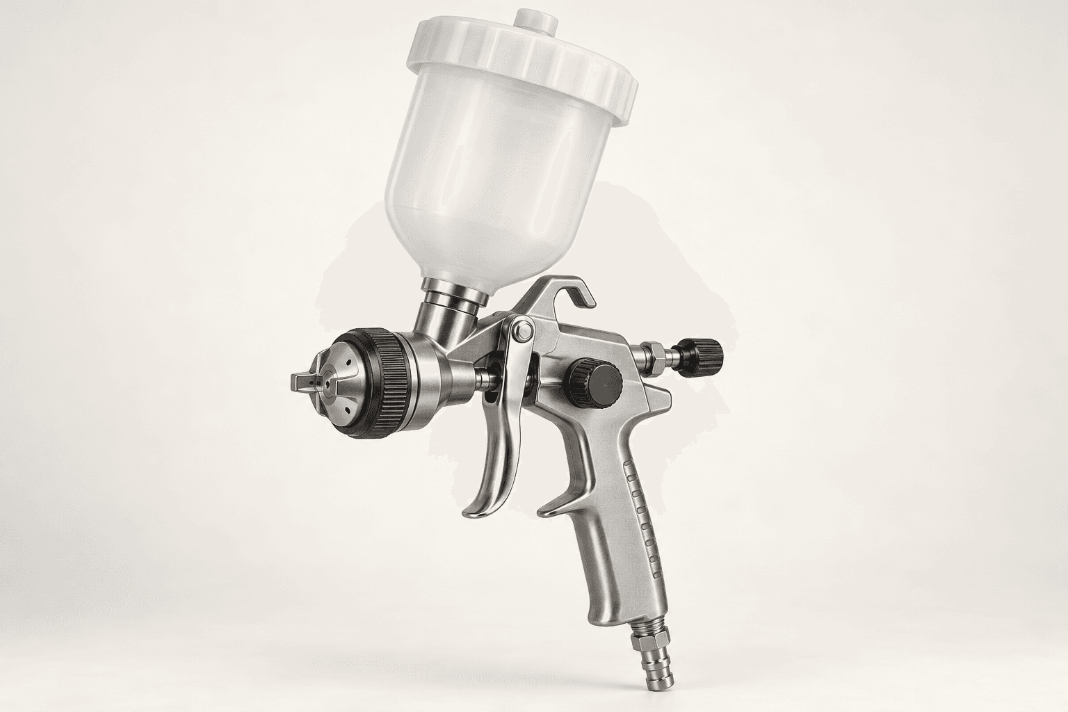
An original educational poster identifies 10 documented construction features. The numbered descriptions remain readable below the artwork on narrow screens.
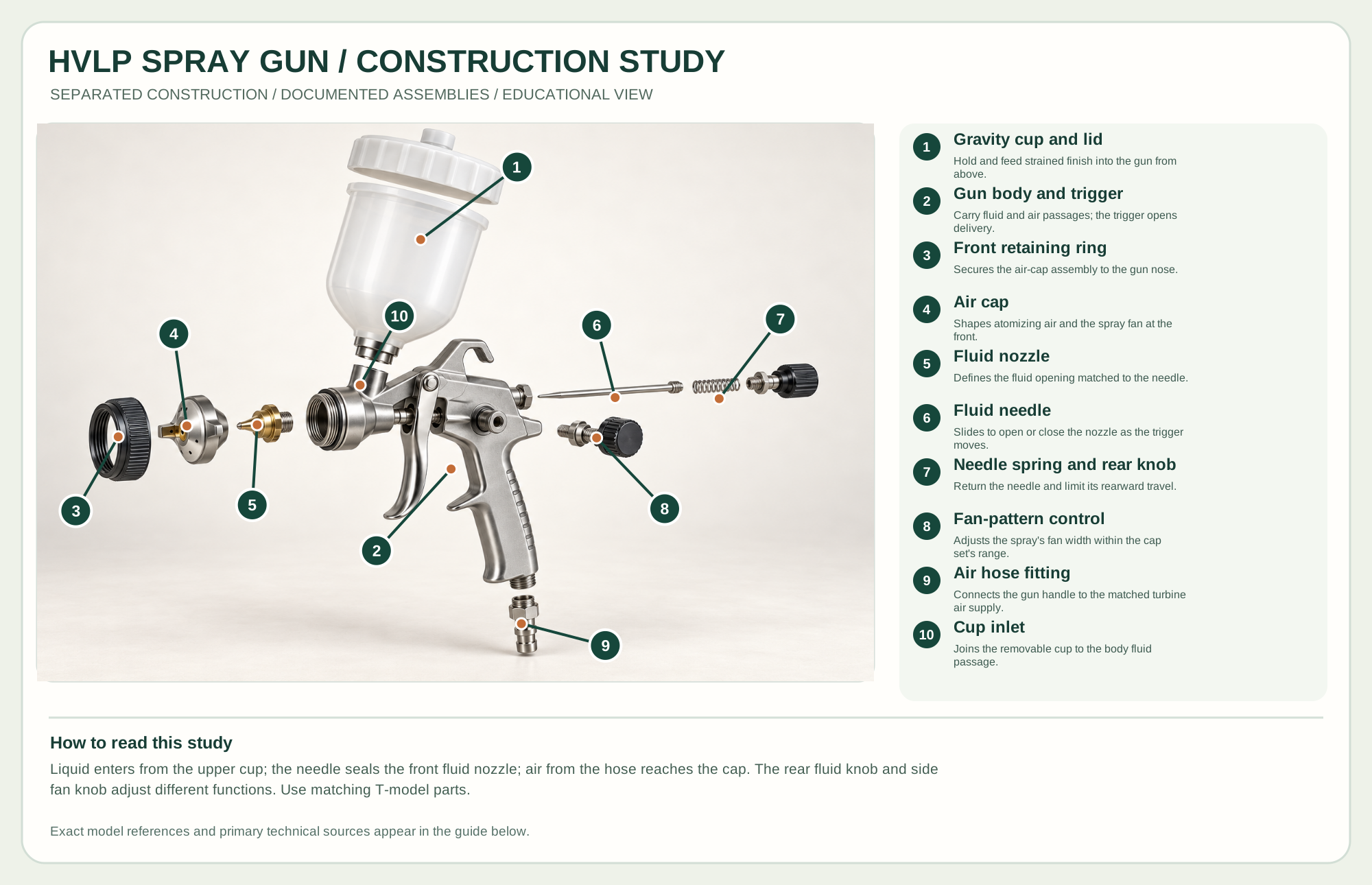
Hold and feed strained finish into the gun from above.
Carry fluid and air passages; the trigger opens delivery.
Secures the air-cap assembly to the gun nose.
Shapes atomizing air and the spray fan at the front.
Defines the fluid opening matched to the needle.
Slides to open or close the nozzle as the trigger moves.
Return the needle and limit its rearward travel.
Adjusts the spray's fan width within the cap set's range.
Connects the gun handle to the matched turbine air supply.
Joins the removable cup to the body fluid passage.
Technical references: Fuji Spray T-70/T-75G T-model user manual and parts diagram · Fuji Spray product catalogue. The external T-model fluid and air-path components are separated along their assembly axes. The trigger stays with the body and inaccessible valve internals are not depicted. This is an educational arrangement, not a cleaning or service order. Original educational artwork depicts documented component groups and their relationships; it is not a service sequence or a replacement for the exact model manual.
An HVLP gun atomizes liquid finish with a high volume of air at comparatively low spray pressure. The Fuji T-75G gravity gun is the documented reference, paired with an appropriate turbine system. Different compressor conversion guns, suction-feed cups and airless pumps require their own instructions; the illustrated gun is not a universal spray-system cutaway.
Liquid descends from the cup toward the fluid nozzle. Pulling the trigger retracts a tapered needle, allowing fluid to pass. Air emerging through the cap breaks it into droplets; the fan control changes pattern shape and the rear fluid knob limits needle travel. Nozzle/needle/air-cap sets must be compatible with the finish and exact gun.
A sealed cup supplies fluid to the gun. Strain the finish and follow the coating maker's viscosity instructions; do not overfill.
The nozzle meters the fluid opening; the tapered needle closes it when the trigger is released. Treat their sealing surfaces as a matched precision set.
The cap shapes atomizing air around the fluid jet; the ring secures its orientation. Its holes must stay clear.
The trigger admits air and pulls the needle. Fluid and fan controls tune delivery and pattern, but do not replace a correctly sized cap set.
A hose fitting connects the gun to the matched turbine supply. Keep the hose path free of sharp bends and tripping hazards.
These decisions make the mechanism useful at the bench.
Read the coating technical data sheet and safety data sheet for compatibility, thinning, ignition controls, ventilation and required protection.
Choose the specified air-cap set, orient the fan, then adjust fluid and fan controls on a test surface with the turbine running.
Hold distance and angle steady, begin motion before triggering, overlap strokes consistently and release after passing the edge.
Controlled overlapping passes can build even coats on doors, panels and casework.
A narrower pattern can reach chair rails, turnings and profiles with less wasted finish.
Test panels reveal atomization, dry spray, runs and compatibility before treating a final piece.
Use the steps for a first pass, then inspect the work before changing the setup.
More fluid is not automatically a better pattern. Tip size, viscosity, air supply and speed interact.
Changing fan width does not make an incompatible coating or nozzle set suitable.
HVLP can reduce overspray when configured correctly, but still produces airborne droplets and requires suitable capture and protection.
Gravity cups sit above the gun; bottom-feed guns draw fluid from below and use different cup fittings.
Turbine guns need a compatible turbine; compressor conversion guns use regulated clean, dry compressed air.
Sets vary by coating and model. The T-series manual identifies matched replacement parts; do not assume cross-brand interchange.
Secure the work, protect sharp edges and release any stored clamping pressure before adjustment or maintenance.
Stop; inspect cup seal/vent, cap holes, nozzle cleanliness, viscosity and supply air.
Reduce delivery or slow dwell; check pass overlap, distance and coating recommendations.
Check air/fluid balance, distance, room conditions and the coating's allowed thinning.
Use the exact model documentation for setup, limits and replacement parts. These lessons, documents and model pages teach relevant techniques or help compare real variations.
Maker video and written instructions for cleaning an HVLP gun.
Maker explanation of fluid and air balance.
Official gun and cap-set comparison.
Primary safety guidance on coating hazards and controls.
Primary guidance for respiratory and other protection selection.
These maker-owned links document relevant tools and tool brands. A product brand may use another company's factory; compare the exact model before choosing parts or accessories.
Handles, irons, saw plates, clamping pads and other replacements vary by maker and model. Use the maker's documentation before changing a component.
Compare the Spray Finishing Tools family →Continue through the Tools library