
Infeed and outfeed beds
The infeed table sets cut depth; the outfeed table must align with the knife's highest cutting path. Coplanar tables and correct outfeed height are central to accuracy.
Make a flat reference face and straight edge by understanding the two beds, fence, guard and cutterhead.
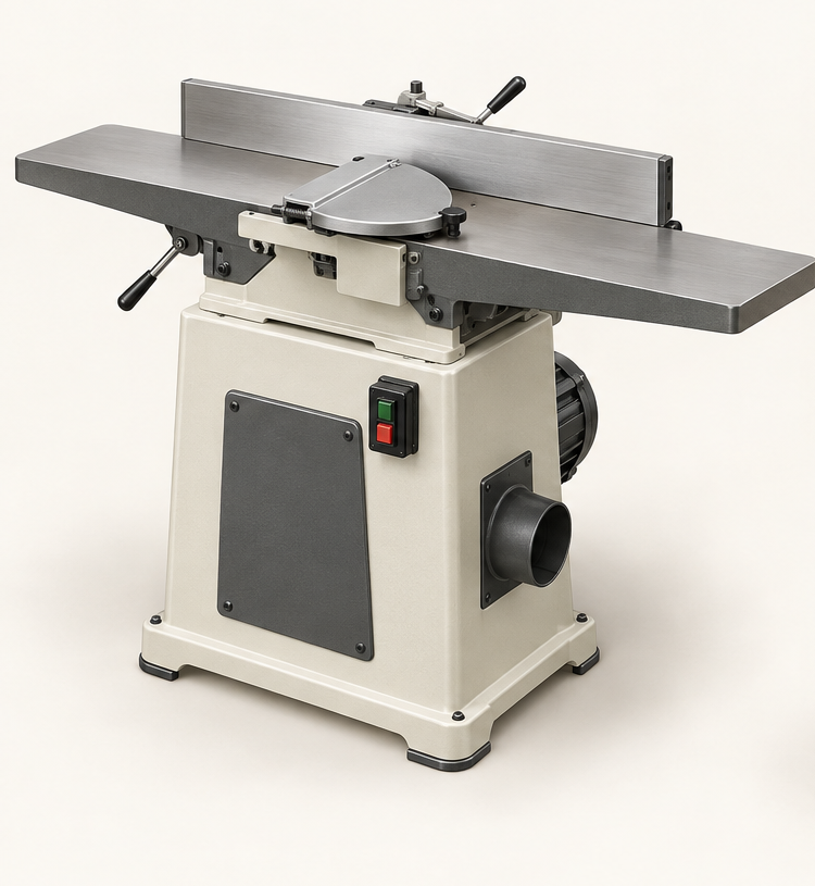
An original educational poster groups twelve model-grounded parts and systems. The numbered descriptions remain readable below the artwork on narrow screens.
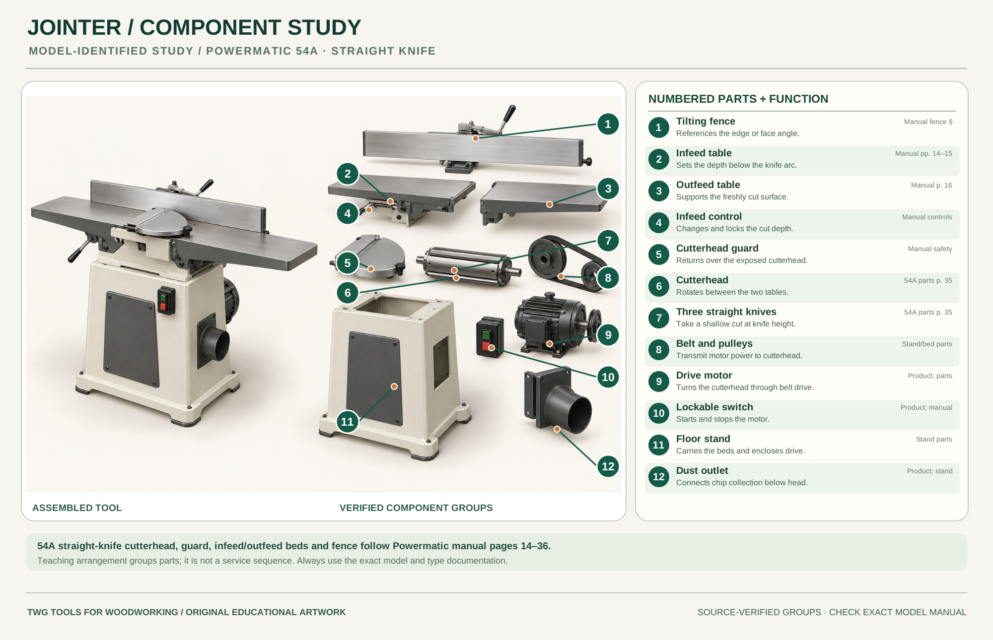
References the edge or face angle.
Manual fence §Sets the depth below the knife arc.
Manual pp. 14–15Supports the freshly cut surface.
Manual p. 16Changes and locks the cut depth.
Manual controlsReturns over the exposed cutterhead.
Manual safetyRotates between the two tables.
54A parts p. 35Take a shallow cut at knife height.
54A parts p. 35Transmit motor power to cutterhead.
Stand/bed partsTurns the cutterhead through belt drive.
Product; partsStarts and stops the motor.
Product; manualCarries the beds and encloses drive.
Stand partsConnects chip collection below head.
Product; standTechnical references: Powermatic 54A and 54HH operating and parts manual (54A sections) · Powermatic 54A official product page. Original educational artwork depicts verified component groups and their relationships; it is not a service sequence or a replacement for the exact model manual.
A jointer removes high spots as wood travels over a cutterhead between an adjustable infeed table and a fixed outfeed reference. The Powermatic 54A is a six-inch straight-knife floor jointer with three knives, a long tilting fence and a belt-driven cutterhead. It flattens a face or straightens an edge; it does not produce uniform thickness on the opposite face. Use a thickness planer after making a reliable reference face. The 54HH helical-head variant uses different cutterhead parts and procedures.
The infeed table sits below the knife arc by the selected depth of cut. The guarded cutterhead removes that amount; the outfeed table supports the newly cut surface at the knife's top arc. A fence controls edge squareness. A motor, belt and pulleys drive the cutterhead below the beds. The separated poster is a documented teaching arrangement, not a teardown sequence.
The infeed table sets cut depth; the outfeed table must align with the knife's highest cutting path. Coplanar tables and correct outfeed height are central to accuracy.
The fence supports face-to-edge registration and can tilt for bevels. Lock it and check square with a reliable gauge before edge jointing.
The spring-return guard covers unused cutterhead width. The 54A has three straight knives; the 54HH's helical insert head is a different model.
The motor drives the cutterhead through a belt. The enclosed stand carries the beds and channels chips to the dust outlet.
Know the switch and table locks before feeding stock. Stop and disconnect power before adjustment or knife work.
Push blocks and suitable hold-downs keep hands above and away from the rotating head, especially for face jointing.
These decisions make the mechanism useful at the bench.
With power disconnected, set and lock infeed depth according to the 54A manual. Aggressive passes reduce control and can worsen tearout.
Orient the board so the knife meets rising fibers as gently as practical; test a short pass if grain changes along the length.
Start with secure pressure on the infeed side, then transfer pressure to the newly cut surface over the outfeed bed. Never push down into the cutterhead opening.
Use push blocks and repeated shallow passes, reducing high spots until the whole face registers on the outfeed table.
Reference the flat face against a square fence and keep the edge supported through the entire pass.
Once one face is flat, plane the opposite face parallel. Recheck the board as internal stress can move it.
Use the steps for a first pass, then inspect the work before changing the setup.
The outfeed bed should meet the top of the knife path. Too high or low can taper a board, leave a concave edge or cause a trailing-end gouge.
Jointing removes the high spots that prevent full registration. Do not press a bowed board flat against the infeed bed only to let it spring back afterward.
Reading surface fibers and taking shallow cuts helps reduce tearout; some reversing grain still needs another method.
Flatten a face first, register it on a square fence for an edge, then use the planer for parallel thickness.
This 54A has straight knives. The 54HH shares much of the manual but has a different insert cutterhead; do not combine their knife-setting instructions.
Longer floor beds better support long boards, while benchtop models save space. Useful capacity includes bed length as well as cutter width.
A combo shares a cutterhead but changes table arrangement for thicknessing. Its setup and guards are model-specific.
A hand power planer can trim a door or beam but is not a fixed-reference substitute for flattening furniture stock.
Stop the tool and disconnect power before investigating a fault or changing a part.
Check table alignment, outfeed height, pressure transfer and long-stock support.
Check grain direction, knife sharpness, cut depth and stock condition.
Stop; disconnect and repair the guard before another cut.
Use the exact tool manual for setup, limits and replacement parts. These lessons, documents and model pages teach relevant techniques or help compare real variations.
These maker-owned links document relevant tools and tool brands. A product brand may use another company's factory; compare the exact model before choosing parts or accessories.
Cutters, abrasives, guards, guides, dust fittings and service parts vary by tool. Check the model plate and manufacturer manual before ordering or changing a component.
Compare the Planers & Jointers family →Continue through the Tools library