
Cutterhead and straight knives
Three reversible straight knives cut the top face. Use exact DW735 knife-change and seating instructions; do not substitute a generic helical-head procedure.
Follow the stock through feed rollers and a three-knife cutterhead to make two faces parallel.
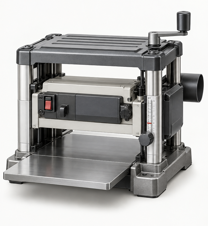
An original educational poster groups twelve model-grounded parts and systems. The numbered descriptions remain readable below the artwork on narrow screens.
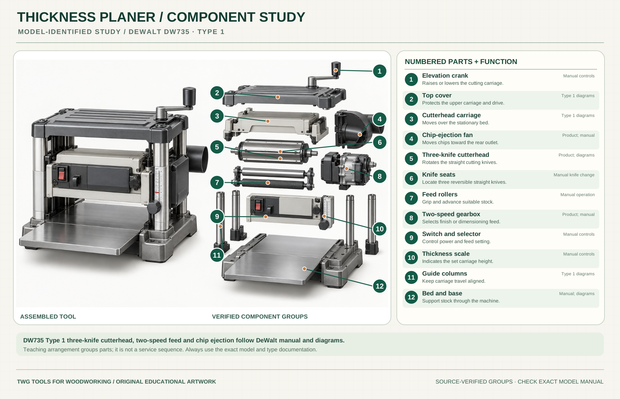
Raises or lowers the cutting carriage.
Manual controlsProtects the upper carriage and drive.
Type 1 diagramsMoves over the stationary bed.
Type 1 diagramsMoves chips toward the rear outlet.
Product; manualRotates the straight cutting knives.
Product; diagramsLocate three reversible straight knives.
Manual knife changeGrip and advance suitable stock.
Manual operationSelects finish or dimensioning feed.
Product; manualControl power and feed setting.
Manual controlsIndicates the set carriage height.
Manual controlsKeep carriage travel aligned.
Type 1 diagramsSupport stock through the machine.
Manual; diagramsTechnical references: DeWalt DW735 Type 1 instruction manual · DeWalt DW735 Type 1 exploded diagram A · DeWalt DW735 Type 1 exploded diagram B. Original educational artwork depicts verified component groups and their relationships; it is not a service sequence or a replacement for the exact model manual.
A thickness planer makes a board's upper face parallel to the lower face riding the bed; it does not, by itself, flatten a warped board. The DeWalt DW735 Type 1 reference uses a 13-inch three-straight-knife cutterhead, two feed settings and fan-assisted chip ejection. Joint or otherwise establish a flat reference face before thicknessing. Longer boards need level support; accessory infeed/outfeed tables are separate from the base DW735 package and may be included in a DW735X kit.
Infeed and outfeed rollers pull stock across the fixed bed under a rotating cutterhead carried by a height-adjustable carriage. The crank changes cut height; the speed selector changes feed rate, not cutterhead speed. A fan sends chips toward the dust outlet. The poster groups Type 1 systems for teaching rather than literal service order.
Three reversible straight knives cut the top face. Use exact DW735 knife-change and seating instructions; do not substitute a generic helical-head procedure.
Rollers grip wood and move it past the knives. Let them carry stock; forced feeding or stock too short for the roller span is unsafe.
The top carriage moves over the stationary bed. Set light passes and use the model's carriage lock or automatic mechanism as specified in its manual.
The selector offers a slower finish feed and a faster dimensioning feed. Follow the manual when changing speed; test the surface rather than assuming the slow setting cures tearout.
The fan-assisted outlet moves a high volume of chips. Attach appropriate collection and keep the exhaust path open.
The lower face registers on the fixed bed. Level infeed/outfeed supports help reduce end snipe, but do not replace a flat starting face.
These decisions make the mechanism useful at the bench.
Joint or use a suitable flattening sled before planing a cupped board; pressure from the rollers can temporarily press warp flat and let it spring back.
Measure the thickest part of the board, set the carriage and respect the DW735 width/depth chart. Thin, wide or figured stock needs extra care.
Keep stock entering and leaving level with the bed. Allow the rollers to feed without lifting, pressing down or pulling the board.
After creating a flat face, take repeated shallow passes and alternate grain-appropriate orientation where needed.
Mill pieces of similar width and thickness together; measure after cuts and let wood movement settle before final passes.
The slower feed can improve knife marks on suitable stock; a very light finishing cut and sharp knives matter too.
Use the steps for a first pass, then inspect the work before changing the setup.
The planer references the underside. A bowed board can emerge similarly bowed but thinner; flatten one face first.
Extra cut near board ends can follow unsupported stock or carriage movement. Keep supports level, use correct feed and allow sacrificial length when practical.
Grain reversal and dull knives can lift fibers. Try shallower cuts, another feed orientation or stock preparation; never force a jam.
The two rates change cuts per inch. They do not change maximum depth or make an unsafe board suitable.
Larger floor machines may offer wider cuts and heavier tables; support, dust and knife requirements still follow exact models.
The DW735 uses three straight knives. Aftermarket cutterheads and other models differ in parts, setup and warranty implications.
The X kit includes accessories such as infeed/outfeed tables; check the purchased package rather than assuming every DW735 includes them.
A jointer makes a flat face or straight edge; a planer references that face to make a parallel opposite face.
Stop the tool and disconnect power before investigating a fault or changing a part.
Check support level, stock length, carriage setting and feed; allow trim length if needed.
Inspect grain direction, knife edges, cut depth, stock moisture and feed setting.
Stop and check port, hose, collection capacity and blockage; never reach in while connected.
Use the exact tool manual for setup, limits and replacement parts. These lessons, documents and model pages teach relevant techniques or help compare real variations.
Official controls, feed settings, cut limits, knife changes and safety.
Official component diagrams used to verify cutterhead, carriage, rollers and chip-ejection groups.
These maker-owned links document relevant tools and tool brands. A product brand may use another company's factory; compare the exact model before choosing parts or accessories.
Cutters, abrasives, guards, guides, dust fittings and service parts vary by tool. Check the model plate and manufacturer manual before ordering or changing a component.
Compare the Planers & Jointers family →Continue through the Tools library