
Motor and drive
The RP2301FC drawing separates field, armature, fan and bearing groups inside its motor housing.
See how guide posts, springs, a lock and staged depth stops let a cutter enter the work under control away from an edge.
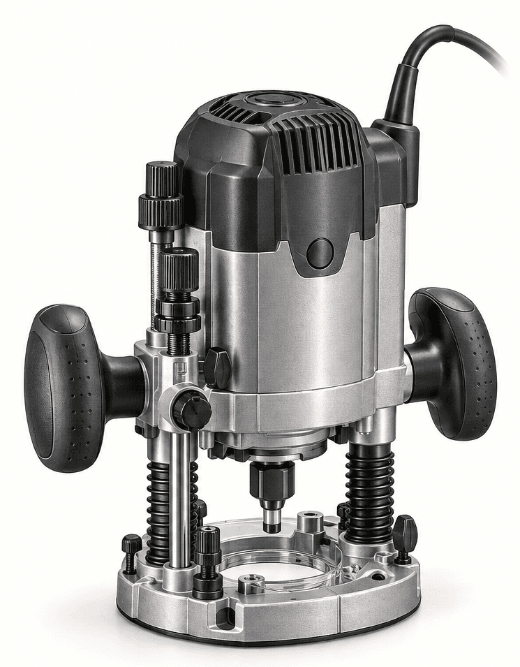
An original educational poster groups twelve model-grounded parts and systems. The numbered descriptions remain readable below the artwork on narrow screens.
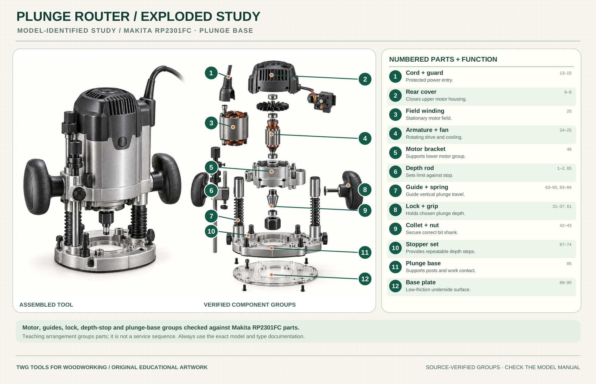
Bring power into the tool through a guarded entry.
Parts 13–15Protects the upper motor and electronic control area.
Parts 6–8Stationary field surrounds the armature.
Part 20Rotate the spindle and move cooling air.
Parts 24–25Supports the lower motor and connects it to plunge hardware.
Part 46Contacts a selected stop to limit plunge travel.
Parts 1–2, 65Guide vertical travel and return the motor upward.
Parts 63–65, 83–84Give hand control and hold the selected depth during the pass.
Parts 31–37, 61Clamp a bit with the matching shank size.
Parts 42–43Provides selectable depth limits for staged cuts.
Parts 67–74Carries posts, stops and work-contact structure.
Part 85Provides the smooth underside around the cutter opening.
Parts 89–90Technical references: Makita RP2301FC official parts breakdown · Makita RP2301FC manual. Original educational artwork depicts verified component groups and their relationships; it is not a service sequence or a replacement for the exact model manual.
A plunge router begins with the bit above the work and lowers its motor along guide posts to a preset stop. It suits stopped grooves, mortises and pockets that cannot simply be entered from an outside edge. A fixed-base router holds one selected height; it does not gain controlled plunge travel merely because it has a depth adjuster.
The motor and collet rotate the bit while the motor bracket slides relative to the base along guide posts and springs. A depth rod meets an adjustable stopper; the plunge lock holds the chosen travel position. On the RP2301FC, the official product documentation specifies three preset depth stops and 0–2¾-inch plunge capacity. This teaching arrangement groups parts and does not prescribe disassembly order.
The RP2301FC drawing separates field, armature, fan and bearing groups inside its motor housing.
The paired guides support vertical travel and return the motor upward when released.
The rod and rotating stop arrangement set a repeatable lower limit for staged cuts.
The lever secures height during a cut. Test that it holds before starting.
The model uses matching 1/4- and 1/2-inch bit holding options and a broad base plate.
Two grips maintain control while the switch and lock remain accessible; route the cord clear of the work.
These decisions make the mechanism useful at the bench.
With power disconnected, lower the bit to a safe reference point, set the depth rod and stopper, then verify the actual depth on scrap.
Use the preset stops to remove material in progressively deeper passes rather than forcing the final depth at once.
Enter under control with the base stable, lock the plunge at depth, guide the cut, then release and allow the bit to rise clear before stopping.
Mark both ends, set travel and guide, enter inside the marked span and release before the far end.
Use a suitable straight/spiral bit, template or fence, and shallow passes with waste clearance.
Confirm bushing or bearing offset, template thickness and bit clearance before the first plunge.
Use the steps for a first pass, then inspect the work before changing the setup.
The paired guide and spring system controls vertical movement; roughness or uneven return calls for service, not extra force.
The stop turret is a reference, not a substitute for measuring the result. Check first cuts and adjust in small increments.
Bit diameter, flute length and chip clearance determine how deeply and quickly a pocket can be cut.
Use the maker's compatible dust nozzle where practical; keep hoses clear of handles, plunge travel and guide.
Some routers use a motor shared with a separate plunge base; the RP2301FC is a dedicated plunge reference model.
Depth rods, micro adjusters and turret counts differ. Follow the controls shown in the exact manual.
The reference model offers 1/4- and 1/2-inch options. Match shank, collet and rated bit size.
Template offset and mounting systems vary. Test clearances before a powered cut.
Stop the tool and disconnect power before investigating a fault or changing a part.
Unplug; inspect guide cleanliness, spring return and base alignment.
Check stop rod contact, lock, template seating and bit slippage.
Reduce cut load; inspect bit sharpness, speed, feed and chip clearance.
Use the exact tool manual for setup, limits and replacement parts. These lessons, documents and model pages teach relevant techniques or help compare real variations.
Official operation, depth-stop and safety instructions.
Official numbered drawing for motor, guides, springs, stopper and base.
Plunge capacity, preset stops, controls, collets and accessories.
Maker overview of plunge routing uses and model variation.
WoodWorkers Guild of America demonstrates setting a plunge router's cut depth with a drill bit or spacers.
WoodWorkers Guild of America demonstrates the plunge stop rod and turret, controlled entry and stopped cuts.
WoodWorkers Guild of America shows a repeatable plunge-depth setting using bar stock between stop rod and turret.
These maker-owned links document relevant tools and tool brands. A product brand may use another company's factory; compare the exact model before choosing parts or accessories.
Bits, belts, sleeves, guides, dust fittings and service parts vary by tool. Check the model plate and manufacturer manual before ordering or changing a component.
Compare the Routing family →Continue through the Tools library