
Sanding sleeve and drum
Sleeve size changes the radius of the contact area. Mount the corresponding support drum, washers and fasteners per the manual.
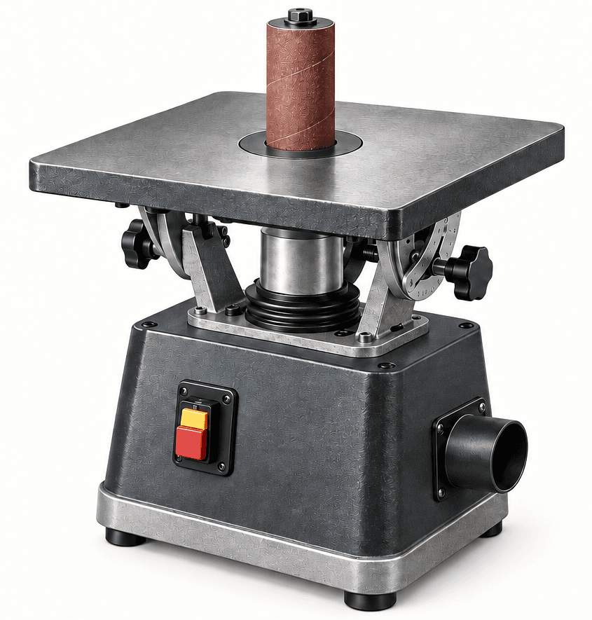
Use a rotating, oscillating sanding sleeve to refine inside curves while keeping the work supported on a properly set table.
An original educational poster groups twelve model-grounded parts and systems. The numbered descriptions remain readable below the artwork on narrow screens.
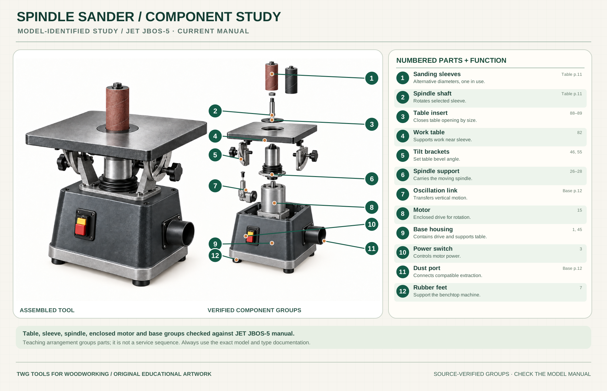
Select one diameter for the intended curve; the second depicted sleeve is an alternative.
Manual p. 11Rotates and oscillates the installed sleeve.
Manual p. 11Closes the opening around the selected spindle size.
Parts 88–89Supports the work and may be tilted for bevel sanding.
Part 82Hold the table at the selected angle.
Parts 46, 55Carries the spindle through its guided movement.
Parts 26–28Represents the documented vertical-motion system without specifying hidden geometry.
Manual p. 12Drives the spindle from inside the machine base.
Part 15Supports table and encloses the motor and drive.
Parts 1, 45Controls motor power at the base front.
Part 3Connects to compatible collection equipment.
Manual p. 12Support the machine on a stable bench and help limit movement.
Part 7Technical references: JET JBOS-5 official manual, table and base/motor drawings. Original educational artwork depicts verified component groups and their relationships; it is not a service sequence or a replacement for the exact model manual.
A spindle sander presents a narrow cylindrical abrasive sleeve to a curved workpiece. The JET JBOS-5 rotates and oscillates its spindle; this spreads wear and helps reduce stationary scratch patterns. A handheld random-orbit pad suits broad faces; a belt sander removes stock rapidly on larger flat areas. Select a sleeve radius that fits the inside curve without forcing the wood against a tiny contact patch.
A motor enclosed in the base drives the spindle. The spindle carries a selected drum or sleeve through a size-matched table insert. The JBOS-5 also moves the spindle vertically as it rotates. The manual depicts the table assembly and base/motor assembly separately; the poster groups only visible, documented assemblies and does not claim an exact internal oscillation linkage geometry.
Sleeve size changes the radius of the contact area. Mount the corresponding support drum, washers and fasteners per the manual.
The shaft rotates the chosen sleeve and moves through the table opening during oscillation.
The table supports the work while a close-fitting insert reduces the open gap around the spindle.
The table can tilt for bevel sanding; recheck the angle and insert clearance before starting.
The official base drawing locates the motor inside the housing. Service of hidden drive components belongs to the manual.
The port connects compatible extraction; the front switch controls power without reaching near the sleeve.
These decisions make the mechanism useful at the bench.
Choose a sleeve radius no larger than the inside radius; use the matching drum, insert and washers.
Keep the piece flat on the table and move it steadily against the abrasive without pinching the sleeve.
Oscillation already shifts contact vertically; move the work around the curve and avoid dwelling at one point.
Leave a small machining allowance and sand to a fair line without pushing hard enough to deflect the spindle.
Choose the largest sleeve that fits the profile and keep the work on the table through the entire sweep.
Set and lock table tilt, check sleeve/insert clearance, then test on scrap before the actual part.
Use the steps for a first pass, then inspect the work before changing the setup.
A small diameter reaches tight curves but concentrates pressure; a larger fitting drum can leave a smoother arc.
The JBOS-5 manual specifies 30 oscillations per minute and a 1-inch stroke. These numbers are model-specific, not universal.
The reference table tilts to 45 degrees; a bevel changes sleeve-to-table clearance, so check it unpowered.
Use appropriate sleeve grit and maintain extraction. Replace worn or torn sleeves instead of increasing pressure.
The JBOS-5 manual lists five included spindle/sleeve diameters; 3 inches is optional. Inventory depends on package and model.
Some machines switch between spindle and edge-belt modes. Their changeover and guards differ from this dedicated spindle reference.
Check the actual machine; oscillation rate and stroke are not interchangeable across brands.
The cited JET manual is edition 13 for serial numbers 20102451 and higher. Verify the plate before relying on a part number.
Stop the tool and disconnect power before investigating a fault or changing a part.
Check sleeve wear, table support, feed pressure and whether the sleeve radius matches the shape.
Stop and unplug; inspect drum, washers, sleeve fit, bench mounting and spindle condition.
Check the insert, port, hose and extractor airflow for obstruction.
Use the exact tool manual for setup, limits and replacement parts. These lessons, documents and model pages teach relevant techniques or help compare real variations.
Current model identity and manufacturer resource hub; use the manual for detailed mechanics.
A separate oscillating spindle design for comparing sleeves and included accessories.
WOOD Magazine demonstrates changing spindle drums and using an oscillating sleeve to refine inside curves; check thread direction in the exact machine manual.
Fine Woodworking demonstrates where an oscillating spindle sander works well and shows a jig for straight edges.
A second model's official sleeve, insert, setup and dust-collection instructions for comparing configurations; check the regional electrical rating.
These maker-owned links document relevant tools and tool brands. A product brand may use another company's factory; compare the exact model before choosing parts or accessories.
Bits, belts, sleeves, guides, dust fittings and service parts vary by tool. Check the model plate and manufacturer manual before ordering or changing a component.
Compare the Sanding family →Continue through the Tools library