
Frame, bed and spoilboard
The rigid base and hybrid table support a replaceable work surface. Surface the spoilboard only when needed so it is parallel to the machine's XY travel.
Connect the digital toolpath to the real gantry, cutter, spoilboard and workholding before making a repeatable cut.
An original educational poster identifies 8 documented construction features. The numbered descriptions remain readable below the artwork on narrow screens.
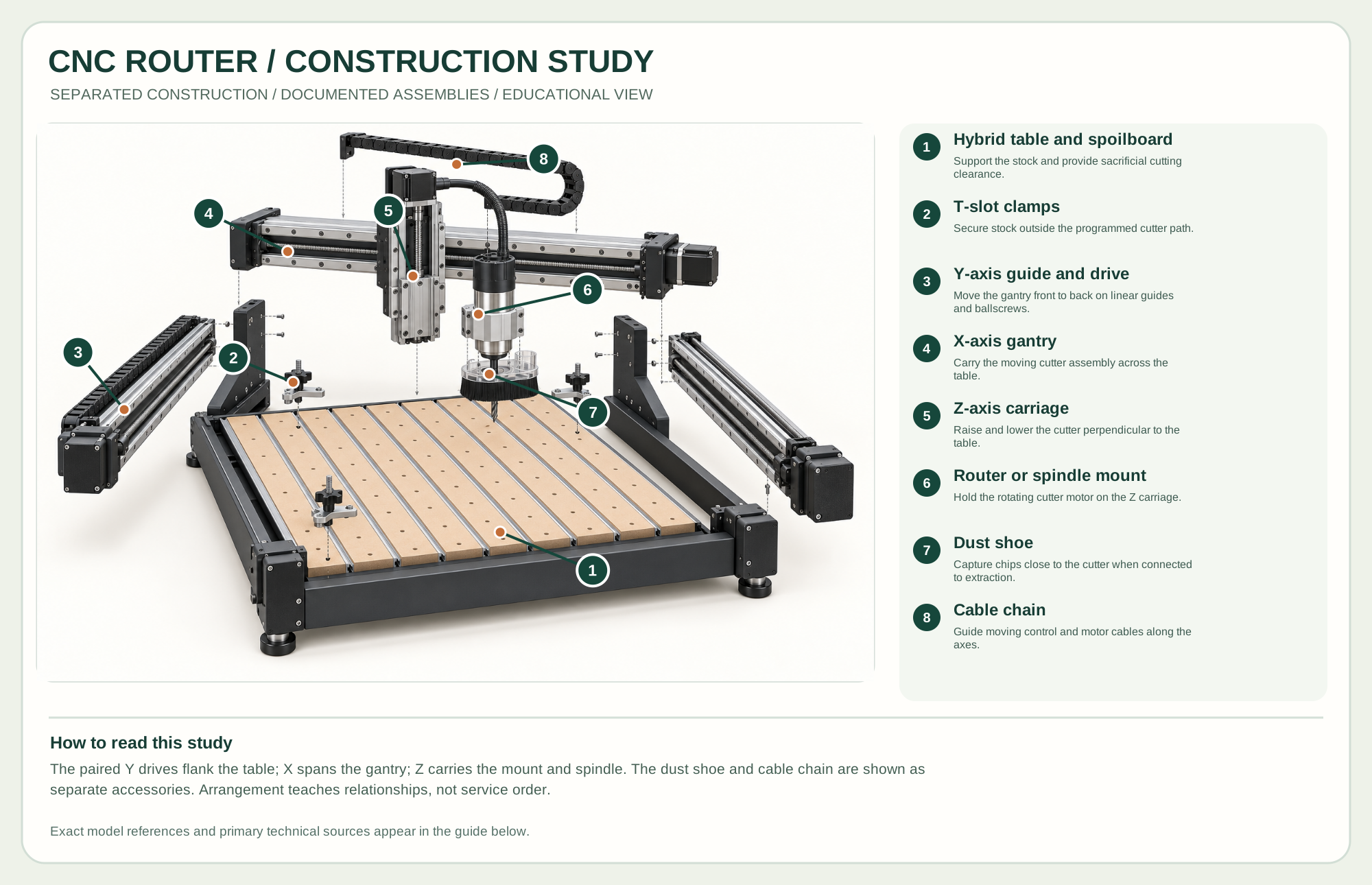
Support the stock and provide sacrificial cutting clearance.
Secure stock outside the programmed cutter path.
Move the gantry front to back on linear guides and ballscrews.
Carry the moving cutter assembly across the table.
Raise and lower the cutter perpendicular to the table.
Hold the rotating cutter motor on the Z carriage.
Capture chips close to the cutter when connected to extraction.
Guide moving control and motor cables along the axes.
Technical references: Carbide 3D Shapeoko 5.1 Pro technical overview · Shapeoko 5.1 Pro official assembly guide · Sweepy Pro dust-shoe installation. The separated base, paired Y drives, X gantry, Z carriage and cutter group teach the Shapeoko 5.1 Pro class of ballscrew-driven gantry machine. It is an educational component arrangement, not an exact service sequence or a revision-specific fastener drawing. Original educational artwork depicts documented component groups and their relationships; it is not a service sequence or a replacement for the exact model manual.
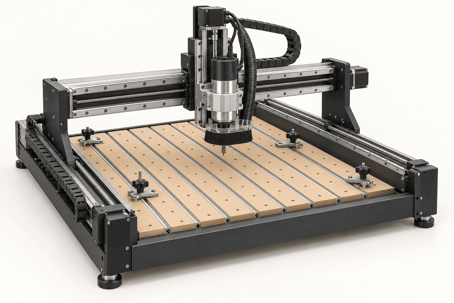
A CNC router moves a rotating bit through programmed X, Y and Z coordinates. It excels at repeatable pockets, signs, templates, cabinet parts and carved surfaces, but cannot correct poor stock holding, a wrong work zero or an unsuitable cutter. The selected Shapeoko 5.1 Pro reference uses a hybrid T-slot table, linear rails and ballscrews on all three axes. The hero depicts that equipment class, not an exact machine photograph or a service drawing.
CAD defines geometry; CAM turns that design into ordered toolpaths, cutter selections and feeds; a controller moves the axes while a router or spindle turns the bit. The gantry carries the X rail, its carriage moves the Z-mounted motor, and the Y drives move the gantry along the table. These independent systems must agree on work origin, units and safe clearance. The dust shoe captures chips near the cutter when connected to extraction.
The rigid base and hybrid table support a replaceable work surface. Surface the spoilboard only when needed so it is parallel to the machine's XY travel.
The reference machine uses linear rails and ballscrews on X, Y and Z. Other CNC routers can use belts, racks or different guides; maintain the drive actually fitted.
A trim router or compatible spindle turns a correctly rated bit. Confirm mount diameter, collet, shank, runout and tool length before a job.
The controller interprets a compatible job file and drives the axes. Homing sensors establish machine position; work zero is a separate, operator-chosen reference.
These decisions make the mechanism useful at the bench.
Choose material size, stock origin, cutter geometry, stepdown, stepover and a postprocessor supported by the controller. Simulate the complete path before cutting.
Keep clamps, screws and hold-downs outside every swept cutter path. Check that the bit can reach the entire program without hitting hardware.
Home the machine if required, set work zero on the real stock, verify Z clearance and run an air-cut or conservative first pass when uncertain.
Produce matched templates, curves, pockets and joinery features from the same reviewed program.
Choose V-bits, end mills or engraving tools according to edge quality and smallest detail.
Machine spoilboard fixtures and drill patterns that improve repeatability on later jobs.
Use the steps for a first pass, then inspect the work before changing the setup.
Homing locates the axes relative to the machine. A CAM origin must still be transferred to the actual stock.
Even a rigid gantry cannot keep a loose blank in position. A small cutter can break or pull work into the path.
Tool diameter, flute count, stickout, wood, rigidity and cut depth interact. Published settings are starting points, not guarantees.
Work envelope, travel, bed construction and material handling change with size. Match the machine to real project dimensions.
A trim router is accessible; a purpose-built spindle may offer a different duty cycle and control. The selected reference accepts compatible options.
These are alternative motion systems. The component poster specifically shows the selected ballscrew and rail class.
Stop the tool and disconnect power before investigating a fault or changing a part.
Recheck CAM origin, work zero, units and toolpath preview before rerunning.
Stop; check holding, stickout, cutter sharpness, engagement and toolpath settings.
Stop the job; inspect obstructions and drive condition, re-home and reset work zero before a new run.
Use the exact tool manual for setup, limits and replacement parts. These lessons, documents and model pages teach relevant techniques or help compare real variations.
Official rail, ballscrew, gantry, bed and cable-chain configuration for the selected reference.
Official checks before cutting, including homing and preparation.
These maker-owned links document relevant tools and tool brands. A product brand may use another company's factory; compare the exact model before choosing parts or accessories.
Cutters, abrasives, guards, guides, dust fittings and service parts vary by tool. Check the model plate and manufacturer manual before ordering or changing a component.
Compare the CNC family →Continue through the Tools library