
Shank and collet
Match nominal sizes and insert the shank to the maker's required depth without bottoming it in the spindle. Never use a mismatched or visibly damaged collet.
Read the shank, edge, flute and bearing geometry so each router bit makes the cut you actually intend.
An original educational poster identifies 8 documented construction features. The numbered descriptions remain readable below the artwork on narrow screens.
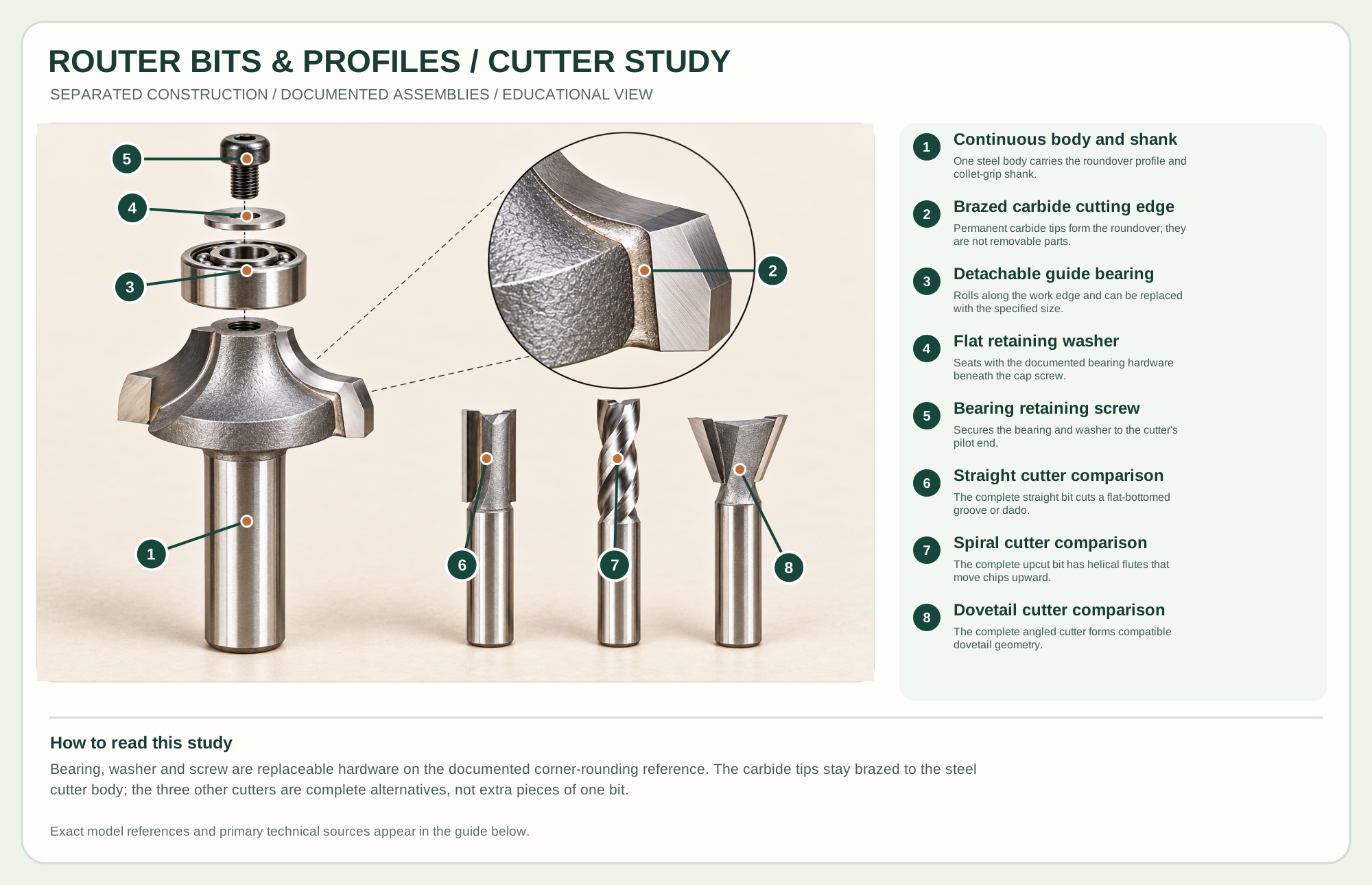
One steel body carries the roundover profile and collet-grip shank.
Permanent carbide tips form the roundover; they are not removable parts.
Rolls along the work edge and can be replaced with the specified size.
Seats with the documented bearing hardware beneath the cap screw.
Secures the bearing and washer to the cutter's pilot end.
The complete straight bit cuts a flat-bottomed groove or dado.
The complete upcut bit has helical flutes that move chips upward.
The complete angled cutter forms compatible dovetail geometry.
Technical references: Freud official router-bit safe working practice and catalogs · Whiteside Machine official router-bit range · Amana Tool 49521 bearing, washer and screw specification · Whiteside essential router-bit set. The bearing-guided roundover study distinguishes a detachable bearing, flat washer and retaining screw from its continuous steel body and permanently brazed carbide cutting tips. Three complete comparison cutters retain their own straight, spiral and dovetail geometries. Original educational artwork depicts documented component groups and their relationships; it is not a service sequence or a replacement for the exact model manual.
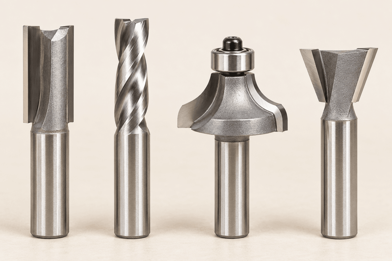
Router bits are replaceable cutting accessories, not motors or machines. A straight bit opens a groove, a spiral bit shears and moves chips along a helix, a bearing-guided roundover shapes an edge, and a dovetail bit cuts an angled wall for a compatible joint. The earlier TWG Router Bits candidate classified nineteen useful profiles; the updated study keeps those distinctions while using the approved tool-guide layout. Actual bit specifications, maximum RPM, shank and collet fit must come from the exact maker marking and instructions.
A router collet grips a clean shank while the cutter's edges remove material in the selected path. Flute geometry affects how chips and surface fibers move; an upcut spiral tends to draw chips upward, a downcut helps protect the top edge, and a compression bit uses opposing shear directions over its specified cutting length. A bearing can guide a compatible edge cut but cannot make an unsupported or excessive pass safe. The poster presents four complete bits side by side, not an exploded assembly.
Match nominal sizes and insert the shank to the maker's required depth without bottoming it in the spindle. Never use a mismatched or visibly damaged collet.
Edge geometry and sharpness determine the cut. A spiral's helix is not automatically upcut or downcut from appearance alone; check product labeling.
A bearing follows a suitable edge or template on bits designed for it. Confirm diameter and template relationship before cutting.
A larger diameter changes the sweep, speed limit and stock engagement. Read the exact bit's maximum speed and take shallow passes.
These decisions make the mechanism useful at the bench.
Decide whether the cut needs a flat floor, clean top face, clean bottom face, shaped edge or matching joint.
Disconnect the router, clean the collet and shank, seat the bit correctly, tighten with the specified wrenches and set only the depth needed.
Use a fence, template, bearing or table setup that supports the stock. Make a shallow test cut, then adjust for grain and chip load.
Straight, spiral, slot, rabbeting, mortising and dovetail bits can make different groove and joint forms when guided correctly.
Roundover, chamfer, cove and ogee bits shape exposed edges; larger profiles often need several passes and strong support.
Flush-trim and pattern bits copy a safe template edge with a bearing positioned for the actual work orientation.
Use the steps for a first pass, then inspect the work before changing the setup.
Upcut and downcut flutes pull chips differently; compression geometry is useful only when its opposed cutting sections engage the intended faces.
It follows a suitable reference surface but does not reduce the load of a full-width deep cut.
A roundover changes only an edge radius; a dovetail needs a matching entry path and cannot plunge arbitrarily into a closed slot.
Straight, upcut spiral, downcut spiral, compression, rabbeting, slot cutter, mortising and dovetail bits address different floor, edge and chip needs.
Flush trim, pattern, roundover, chamfer and cove bits depend on safe base, template or bearing support.
Roman ogee/classical, V-groove, core box, bowl/tray, raised panel and rail-and-stile profiles need compatible stock and often table-mounted setups.
Flat-bottom grooves, dadoes and mortises; match cutting length and diameter to the setup.
Moves chips upward from a slot; support the top face if its fibers lift.
Presses chips toward the cut bottom and can preserve a clean top edge; avoid trapping chips in a deep pocket.
Opposing shear directions protect both faces only when the specified sections engage the material.
Bearing follows a template or reference edge while cutters bring stock flush.
Bearing-guided copy cutting; check whether the bearing sits above or below the edge.
Forms an outside radius; bearing size, cutter radius and depth set the transition.
Cuts a flat bevel; test depth to control the bevel's width.
Forms a concave edge; use shallow passes and back up exit grain.
Cuts a step along an edge for backs, panels or joinery.
Combines curves and flats; choose a profile proportionate to stock thickness.
Cuts angled walls for a guided dovetail or sliding joint; entry and exit geometry matter.
Makes an angled channel for lettering or decorative lines; depth changes line width.
Produces a rounded-bottom groove or channel of a specified radius.
Side cutters make a narrow slot for splines or panels; arbor and bearing must match.
Straight or spiral cutter clears a pocket in shallow passes with chip evacuation.
Large-radius cutter makes a shallow dished surface; use strong support and maker limits.
Large panel-edge profile usually needs an appropriate router table, speed and repeated passes.
Matched profile pair makes mating frame members; test the fit before production.
Stop the tool and disconnect power before investigating a fault or changing a part.
Stop; inspect sharpness, RPM, depth, feed, bearing and work support.
Check grain, flute direction, depth and use a test pass or suitable backer.
Stop; clean and inspect the matched shank and collet, then reinstall by the exact manual.
Use the exact tool manual for setup, limits and replacement parts. These lessons, documents and model pages teach relevant techniques or help compare real variations.
Official downloads include cutter safety and handling instructions; use the PDF that matches the actual bit.
Official profile families, bit dimensions and application descriptions.
Maker source for straight, spiral, guided and specialty cutter families.
Official additional descriptions of bit types and accessories.
Manufacturer demonstration of bit forms and cut results; use written maker instructions for actual setup and limits.
These maker-owned links document relevant tools and tool brands. A product brand may use another company's factory; compare the exact model before choosing parts or accessories.
Cutters, abrasives, guards, guides, dust fittings and service parts vary by tool. Check the model plate and manufacturer manual before ordering or changing a component.
Compare the Routing family →Continue through the Tools library