
Enclosure and lid
The enclosure contains access to the beam and fumes. Use the installed lid, shielding and interlocks exactly as documented; never defeat an interlock.
Understand the enclosed work area, beam delivery, focus and exhaust before engraving or cutting wood-based material.
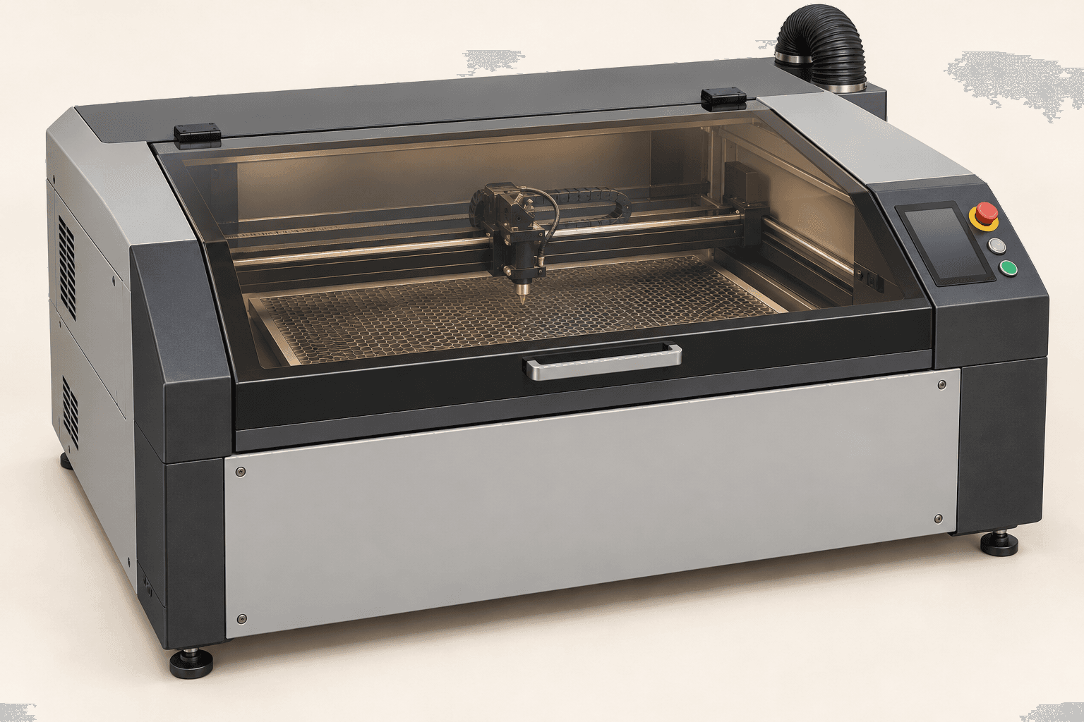
An original educational poster identifies 7 documented construction features. The numbered descriptions remain readable below the artwork on narrow screens.
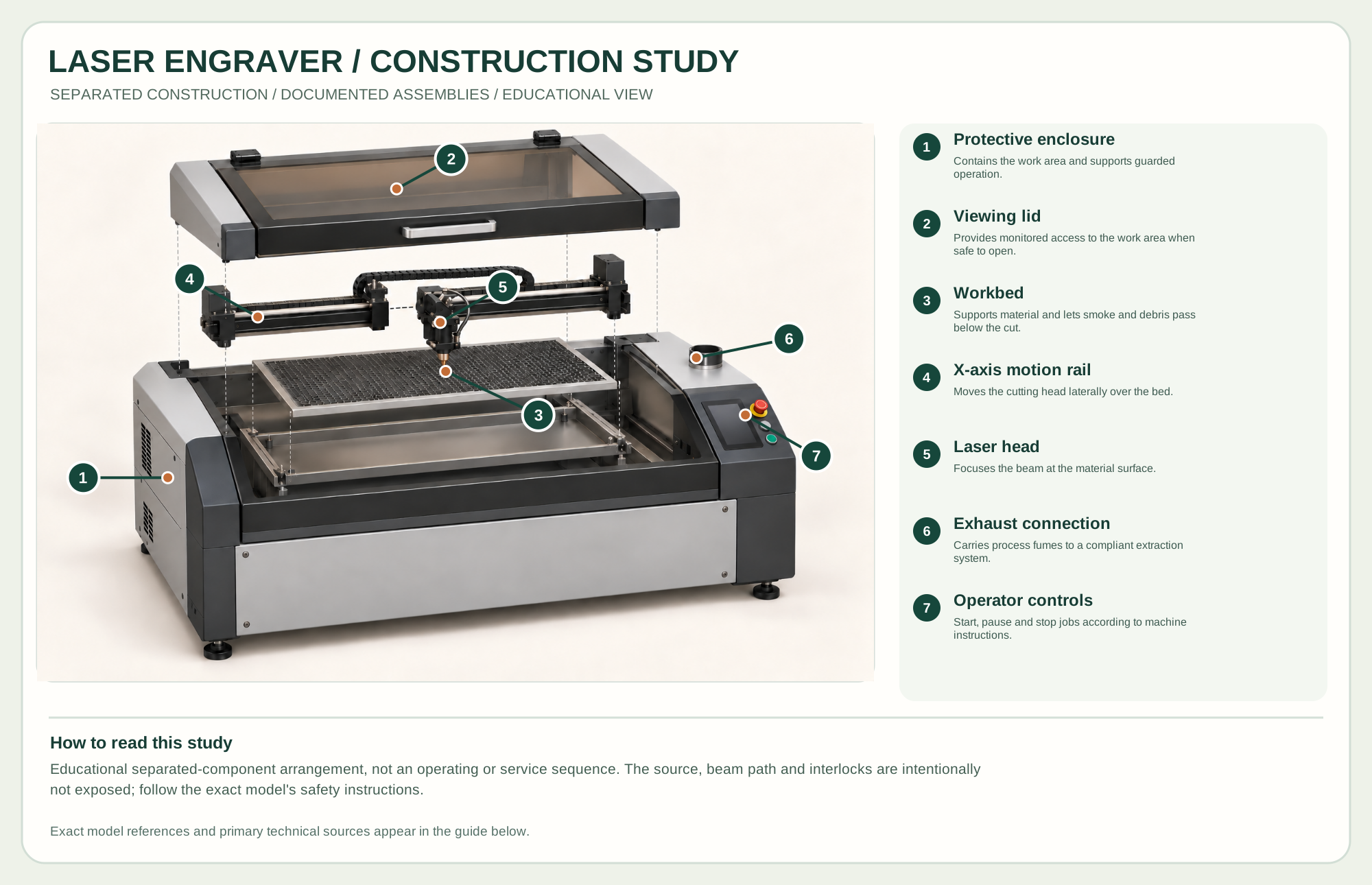
Contains the work area and supports guarded operation.
Provides monitored access to the work area when safe to open.
Supports material and lets smoke and debris pass below the cut.
Moves the cutting head laterally over the bed.
Focuses the beam at the material surface.
Carries process fumes to a compliant extraction system.
Start, pause and stop jobs according to machine instructions.
Technical references: Epilog Fusion Edge official manuals · Epilog Fusion Edge exhaust requirements · Epilog Fusion Edge X-axis assembly reference. The lid, X rail, closed head and removable bed are shown apart from the protective enclosure to teach their physical relationships in an enclosed CO2 laser configuration. Hidden source and optics remain closed and are not depicted as an invented beam path. Original educational artwork depicts documented component groups and their relationships; it is not a service sequence or a replacement for the exact model manual.
A laser engraver removes or darkens material by concentrating light at the surface while the head follows a digital path. It can make lettering, templates, veneer pieces and thin cuts without a rotating bit, but it creates smoke, heat and ignition risk. The selected technical reference is an enclosed Epilog Fusion Edge CO₂ configuration. Open-frame diode, fiber and pass-through machines can have different beam, enclosure and safety requirements; do not transfer specifications between them.
The CO₂ source sends a beam along an enclosed optical path through mirrors to a focusing head. X/Y motion positions the focus over a supported workpiece. An enclosure, lid interlocks, exhaust and operator controls work together in the selected machine configuration. The exterior poster identifies only visible groups; the optical path is illustrated separately as a conceptual schematic, never as a service alignment procedure.
The enclosure contains access to the beam and fumes. Use the installed lid, shielding and interlocks exactly as documented; never defeat an interlock.
A CO₂ source, mirrors and head deliver energy to the stock. Keep lenses and mirrors clean only by maker instructions, and set focus for actual material thickness.
The bed supports stock below the moving head. Honeycomb or slat supports reduce contact, but accumulated scraps can ignite.
Exhaust removes smoke from the enclosure; air assist can clear the kerf and reduce flare-ups where fitted. The extraction requirement is model and installation specific.
These decisions make the mechanism useful at the bench.
Know the exact substrate, adhesive and coating. Do not process unknown plastics or materials prohibited by the machine maker.
Clean and support stock, set focus by the manual, then test power and speed on a small offcut before the final design.
Keep exhaust running and watch for flame, abnormal smoke or loss of airflow. Pause or stop immediately when behavior changes.
Produce lettering, alignment marks and decorative surfaces on compatible wood stock.
Cut fine shapes and templates after testing char, kerf and adhesive response.
Use nests and a clean bed for batch runs, keeping the cut pieces supported until completion.
Use the steps for a first pass, then inspect the work before changing the setup.
Diode, CO₂ and fiber sources interact differently with wood and other materials. Match the process to the exact installed source.
A strong beam does not compensate for poor extraction. Follow maker airflow and venting requirements for the exact model.
A laser leaves a finite cut width and heat-affected edge. Make a test joint before cutting a full set of parts.
The selected reference delivers a beam through mirrors within a guarded enclosure.
Some are open frame and require a separately designed enclosure and ventilation. Do not assume they share this machine's safeguards.
Only models explicitly equipped and rated for these workflows should be used that way.
Stop the tool and disconnect power before investigating a fault or changing a part.
Check focus, material thickness, clean optics and tested settings; do not blindly increase power.
Stop, inspect the exhaust flow and material suitability, then follow maker guidance.
Pause; confirm file size, origin, stock position, focus and machine maintenance before retrying.
Use the exact tool manual for setup, limits and replacement parts. These lessons, documents and model pages teach relevant techniques or help compare real variations.
Maker's manual hub; select the revision that matches the purchased machine.
Model-specific exhaust sizing and connection guidance.
These maker-owned links document relevant tools and tool brands. A product brand may use another company's factory; compare the exact model before choosing parts or accessories.
Cutters, abrasives, guards, guides, dust fittings and service parts vary by tool. Check the model plate and manufacturer manual before ordering or changing a component.
Compare the Laser family →Continue through the Tools library