Simple Wooden Box
An illustrated TWG box-build lesson for reading five prepared parts, checking the fit, and understanding the adult-controlled fastening path.
Finished outcome: An open-top box with listed outside dimensions of 8 × 5 × 3 in and a 7 × 4 × 2 1/2 in inside cavity; actual fit and intended use are adult-checked.
This original TWG design uses a 1/2 in bottom under four 2 1/2 in walls. The two 8 in long walls stay outside; the two 4 in end walls fit between them. These views explain the listed geometry, not a physical build or load rating. The adult prepares and checks actual stock, selects any fastening setup, controls drilling and screw installation, and decides when the glued assembly is ready for an intended use.
Adult preparation
- Prepare and label the five listed parts. Measure the actual stock and parts before assembly; resolve any mismatch rather than relying on the drawing.
- Mark a reference face and edge on each part. The long walls stay outside the 4 in end walls; all walls sit on the bottom's top face.
- Stage eight #6 × 1 1/4 in flat-head wood screws, the selected glue, a square, and suitable adult-set clamps. Before drilling, check the screw maker's current instructions for the actual screw and wood, including clearance through the bottom, lead-hole guidance for the wall, and head recess. This lesson does not choose bit sizes, torque, or a universal end distance.
- For each wall, the TWG layout decision is a pair of locations mirrored about the wall midpoint and centered across its actual thickness. The adult dry-fits the parts, confirms each path lands fully inside sound wall stock and clears the corner joints, edges, splits, and the other screw, then selects actual marks using applicable manufacturer or qualified guidance. If no suitable placement can be confirmed, pause only the drilling/fastening step and continue other safe lesson work.
- Keep a flat cure surface available; the adult follows the chosen glue label for handling and cure timing.
Materials
- 1/2 in clear pine or poplar
- Wood glue
- Eight #6 × 1 1/4 in flat-head wood screws
- Pencil and painter tape
- 80 and 120 grit abrasive
- Paper towel for glue squeeze-out
Tools
- Tape measure and combination square
- Hand sanding block
- Clamps selected and set by the adult
- Adult-controlled drill/driver with product-appropriate clearance-hole and lead-hole bits, countersink, and driver bit
- Dust brush
Parts you'll need
- Bottom: prepare 1 piece measuring 8 in long × 5 in wide × 1/2 in thick. The bottom supports the walls from underneath.
- Long walls: prepare 2 pieces measuring 8 in long × 2 1/2 in wide × 1/2 in thick. These stay outside.
- End walls: prepare 2 pieces measuring 4 in long × 2 1/2 in wide × 1/2 in thick. These fit between the long walls.
- Wall height plus bottom thickness: 2 1/2 in + 1/2 in = 3 in outside height.
- Inside cavity after wall thickness: 8 in − 1 in = 7 in long; 5 in − 1 in = 4 in wide; 2 1/2 in high.
Vocabulary
Reference face
The marked face kept consistent when parts are checked and assembled.
Dry-fit
A test assembly without glue or fasteners.
Square
A corner or object that meets at a true 90-degree relationship.
Before you start: safety
- The adult controls every cut, fastener-layout decision, pilot/clearance hole, countersink, driver, screw installation, structural correction, cure decision, and final-use decision. The adult selects and sets the clamp arrangement; a learner may handle a clamp only after explicit release and with direct supervision.
- Keep every part supported for sanding. The learner does not handle the drill/driver, bits, countersink, or screws during installation and never holds work in a drilling or driving path.
- Wipe glue from hands and the bench with a towel; do not touch eyes after handling glue or dusty parts.
Who does what?
The stage follows the work the learner personally does. Adult-only complexity does not raise the learner's stage.
Child's part
- Match the five prepared parts to the cut list and keep their labels visible.
- Place walls against the reference marks during a dry-fit and describe which end walls fit between the long walls.
- Hand-sand only adult-selected, supported edges when that task is released.
- After tools are put away, point out the bottom-to-wall joint and report any gap, split, proud screw head, exposed point, or misalignment to the adult.
Try with adult approval
- PVA glue application, wiping squeeze-out, and clamp placement or gentle tightening only after the mentor explicitly releases the job; the adult selects and sets the clamp arrangement and directly supervises any released clamp handling. Screw layout, drilling, countersinking, and screw installation are not released.
Always adult-controlled / high-risk
- Verify actual stock and cut dimensions; select and check the two-per-wall screw layout against the real joints and product guidance; control pilot/clearance holes, countersinking, all eight screws, glue cure, structural correction, finish products, and any decision about intended use. This lesson assigns no load capacity.
Teacher / mentor introduction
Put the five labeled parts on the bench and ask what job each part does. Explain that the box works because the bottom controls the footprint and the four walls keep their reference faces consistent.
Demonstration
- Show one hand-sanding pass only after the adult has checked how the actual part is supported.
- Dry-fit one long wall and one end on top of the bottom; show that the end meets the bottom between the long walls.
- Explain the TWG layout rule using the actual dry-fitted parts: two locations per wall, mirrored about its midpoint and aligned with the wall's real footprint. Do not demonstrate a generic end distance or treat a picture as a drilling template.
- Show a section diagram of one screw path: the screw enters from the bottom's underside, passes through the bottom, and continues upward into the wall. Before drilling, the adult resolves the separate clearance hole, wall lead hole, and shallow head recess from current product guidance for the selected screw and actual stock.
Build steps
1. Identify the five parts
Match the bottom, two 8 in long walls, and two 4 in end walls to the cut list. Point to length, width, and thickness, then keep the labels visible. The adult checks actual prepared parts against the list before assembly.
What to notice: The cut list and prepared stock are checked together.
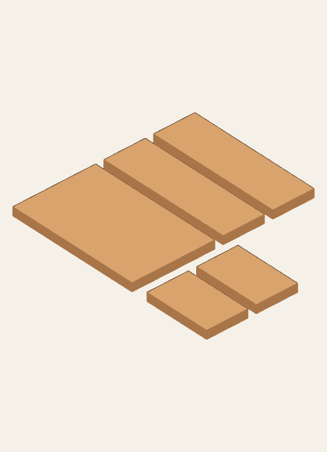
TWG model view · parts before assemblyDimensions are also written here so you do not need to zoom. Compare them with the actual prepared stock. 2. Check the reference faces
Place each supported part with its marked reference face up. The two long walls will stay outside; the shorter end walls will fit between them. Check that the bottom's top face is the surface the walls will sit on.
What to notice: Long walls outside; end walls between.
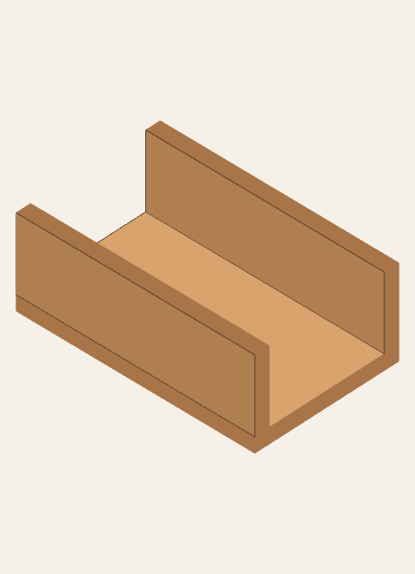
TWG model view · bottom under long wallsThe walls sit on top of the bottom; this is a partial assembly view, not a fastening template. 3. Sand only released edges
Use a hand block on the adult-selected edges with short strokes, when the adult has checked how the part is supported. Keep the reference face marked and brush dust away before checking the edge.
4. Dry-fit the short ends
Place the two end walls between the long walls, all on the bottom's top face, without glue or screws. Check that their ends meet the long walls and that the top edges line up. Measure the outside footprint against 8 in × 5 in; do not force a mismatch closed.
What to notice: Short ends close the gaps between the outside long walls.
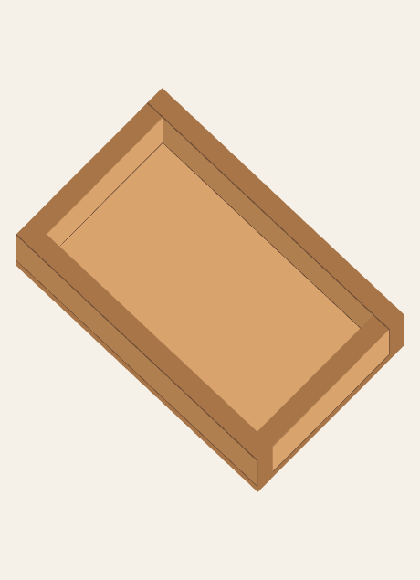
TWG model view · dry-fit relationshipCheck the actual fit, 8 by 5 inch outside footprint, and aligned top edges before glue. 5. Check the fastening path and layout
The TWG design calls for eight #6 × 1 1/4 in flat-head screws, two per wall. For each wall, the adult chooses a pair mirrored about its midpoint and centered across the actual wall thickness. With the real dry-fit, the adult checks that each path stays inside sound wall stock and clears the wall ends, corner joints, edges, splits, and the other fastener. No fixed end distance or coordinates are supplied. If product or qualified guidance does not support suitable placement in the actual stock, pause only the committed assembly steps; safe part-identification, sanding, or reflection work may continue.
What to notice: The next step shows the path; it does not mark locations.
6. Glue and align the walls
After the adult confirms a fastening layout can be used with the actual parts, and if the mentor releases the task, apply the selected glue only as its label directs, bring each wall to the reference faces, and wipe squeeze-out under instruction. The adult sets the clamp arrangement; learner clamp handling is optional and requires explicit release and direct supervision.
7. Adult prepares and installs the screws
Before drilling, the adult follows the selected screw maker's current guidance for a clearance hole through the bottom, a separate lead hole into the wall, and a shallow countersink for the flat head. Hole and bit choices depend on the actual screw and wood; the technical reference below explains that these are distinct checks, not a bit-size prescription for this box. The adult then installs the eight screws upward from the underside into the four wall edges and checks each stopped joint before proceeding.
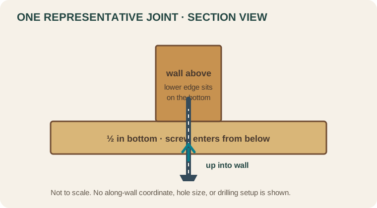
TWG section diagram · preparation varies by screw and woodThe USDA Forest Products Laboratory describes separate shank-clearance and threaded lead-hole considerations; use the current screw maker's instructions for the actual materials. 8. Check fit and square
After the driver is put away, the learner checks two inside corners with a square and compares the outside length and width with the 8 in × 5 in design. Confirm that the walls remain on top of the bottom and that no joint has opened. The adult handles any correction and records deviations; this lesson assigns no arbitrary tolerance.
9. Inspect and record the glue status
With tools put away, check the actual assembly for splits, breakout, open joints, proud or damaged screw heads, exposed points, and sharp edges. Compare its measurements with the cut list. Record the selected glue and the product-label handling/cure instructions; the adult decides when any later finish or intended use is appropriate. No load rating or universal cure time is assigned.
What to notice: Inspection is based on the actual assembly and the selected product labels.
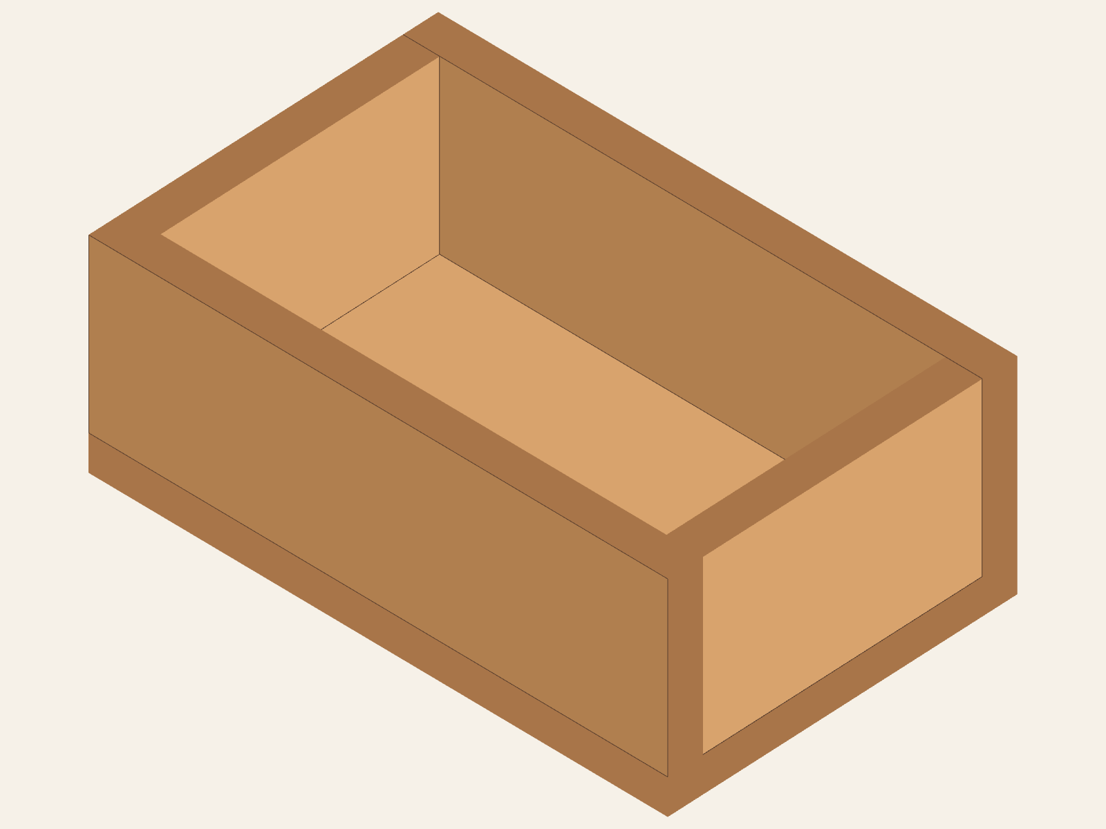
TWG model view · check the real boxGeometry views support discussion only. The adult records product readiness and intended-use decisions.
Sanding sequence
- After cure, inspect first; then hand-sand exposed edges with 120 grit and finish with 180 grit if the adult approves.
- Keep the block flat and sand with the grain. Brush dust away before deciding whether the surface is ready.
Finishing
- The adult chooses whether the box needs a finish and reads the product label, ventilation, cure, and rag-disposal requirements.
- Test any color or sheen on a separate labeled scrap first; do not use an untested product on the box.
Final inspection
- Compare the actual outside dimensions with the 8 in × 5 in × 3 in design and the inside cavity with 7 in × 4 in × 2 1/2 in; this lesson does not define a numeric tolerance.
- Check every wall-to-wall corner and each wall-to-bottom connection for gaps or movement; confirm the walls still sit on the bottom and the actual corners check square.
- Check that fastener heads are seated without crushing or splitting the stock, no point or sharp edge is exposed, and no screw exits an unintended surface.
- Adult records the selected glue's label-directed handling/cure status and makes any decision about later finish or intended use. This lesson does not assign a load capacity.
Common mistakes
- Using 3 in walls and accidentally making the outside height 3 1/2 in.
- Putting the 4 in end walls outside the long walls and making the outside width too wide.
- Skipping dry-fit and discovering a swapped or reversed part after glue.
- Choosing fastener locations before tracing the actual joint, guessing pilot-hole sizes, or using clamp force to correct a measurement mismatch.
What learners should observe
- The 4 in end walls plus the two 1/2 in long-wall thicknesses make the listed 5 in outside width.
- The 2 1/2 in wall height plus the 1/2 in bottom makes the listed 3 in outside height.
- The bottom sits under the walls, and the screw path runs from the underside through the bottom and into a wall.
- A countersink is a head recess, not the same hole as the clearance bore or wall lead hole.
Discussion questions
- Which part controls the box footprint?
- Why are the end pieces shorter than the long sides?
- What check would you repeat before adding a lid?
Assessment and reflection
Learner can match all five parts, explain the bottom-under-walls and long-outside/end-between relationships, describe the upward screw path without choosing a fastener location, and name the actual-assembly checks and adult-controlled steps.
Optional extension / challenge
- Design a removable 8 in × 5 in lid on paper without cutting it.
- Make a label card showing the finished dimensions and intended use.
- Compare a square box corner with one that is visibly out of square.
Cleanup
- Return clamps, square, and driver to their safe storage states.
- Brush dust into the collection point and wipe glue from the bench.
- Store the box on a flat, labeled cure surface with the hardware and cut-list card.
Adapt the lesson
One-on-one
Let the learner choose the box's job and repeat the dry-fit check before the adult assembles it.
Group or classroom
Pre-build kits with labeled parts; one adult runs the glue and fastening station while learners rotate through cut-list reading, sanding, and inspection.