
Head, valve and cylinder
The removable head cover encloses a valve piston and spring above the driver unit and cylinder; these parts require depressurization before service.
Place nearly invisible pins in delicate trim with controlled pneumatic pressure, accurate nose registration and safe sequential actuation.
An original educational poster identifies 10 documented construction features. The numbered descriptions remain readable below the artwork on narrow screens.
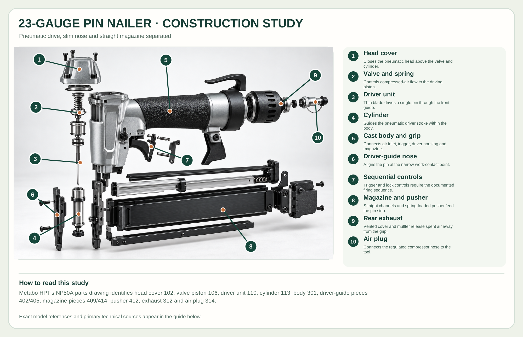
Closes the pneumatic head above the valve and cylinder.
Controls compressed-air flow to the driving piston.
Thin blade drives a single pin through the front guide.
Guides the pneumatic driver stroke within the body.
Connects air inlet, trigger, driver housing and magazine.
Aligns the pin at the narrow work-contact point.
Trigger and lock controls require the documented firing sequence.
Straight channels and spring-loaded pusher feed the pin strip.
Vented cover and muffler release spent air away from the grip.
Connects the regulated compressor hose to the tool.
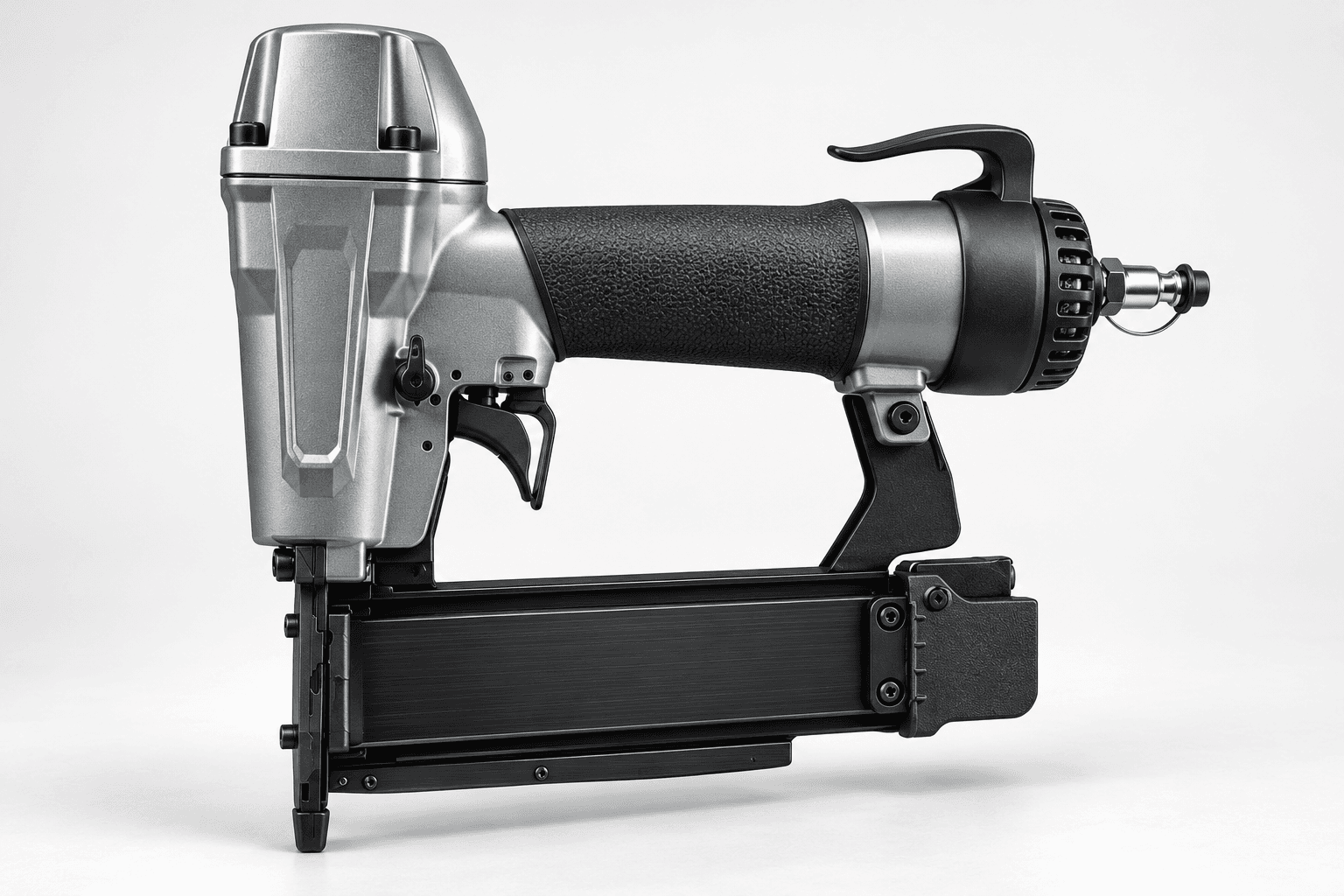
Technical references: Metabo HPT NP50A official parts breakdown · Metabo HPT NP50A owner manual · Metabo HPT NP50A product. Compressed air moves the valve and piston driver through the cylinder toward the slim nose. A pusher advances 23-gauge pins in a straight magazine. The rear assembly is an air exhaust and inlet, not an electric motor. Groups are spaced for education, not for service order. Original educational artwork depicts documented component groups and their relationships; it is not a service sequence or a replacement for the exact model manual.
Metabo HPT's NP50A drives 23-gauge headless pins from 1/2 to 2 inches through a straight 100-pin magazine. Its sequential dual-trigger actuation and dry-fire lockout help deliberate placement. Pins hold light trim while adhesive cures; they are not structural fasteners and may deflect in hard or angled grain. The illustration preserves the model's real pneumatic architecture without branding.
Compressed air enters the rear plug and, when the sequential controls are correctly operated, shifts the head valve to drive a piston and thin driver down the cylinder. The driver pushes one pin from the magazine through the narrow driver guide and nose. A pusher feeds the next strip position. The official parts drawing separates the head cover, valve, driver, cylinder, guide covers, magazine halves, pusher, exhaust and controls; the teaching illustration groups these real parts without prescribing service order.
The removable head cover encloses a valve piston and spring above the driver unit and cylinder; these parts require depressurization before service.
A slim driver guide aligns the pin at the work. A no-mar nose cap protects delicate surfaces when compatible.
The straight magazine holds 23-gauge pins; the pusher advances the strip and a lockout reduces dry firing near empty.
The sequential triggers, lock lever, vented rear exhaust and air plug remain distinct components in the official parts drawing.
These decisions make the mechanism useful at the bench.
Use a regulated supply within the maker's 64–100 PSI range and test drive depth on matched scrap.
Keep the nose square and clear of fingers; plan pin length and angle so it cannot emerge from an edge.
Use the manual's sequential dual-trigger method; do not defeat trigger lock or dry-fire protection.
Apply adhesive, align the trim, and use pins for temporary holding while the bond cures.
Test on scrap to prevent split edges and arrange pin paths away from future cuts.
Use pins for nonstructural alignment only, then add the joinery or fasteners the load requires.
Use the steps for a first pass, then inspect the work before changing the setup.
Dense or angled grain can bend a pin; plan its path and protect the opposite face.
Removing the hose and exhausting pressure precedes any nose or magazine service.
It shows documented valve, driver, magazine and nose groups, not every seal or a reassembly instruction.
The reference accepts 1/2–2 inch pins; choose enough holding depth without risking exit.
Cordless models eliminate an air hose but use different drive mechanisms and weights.
A pin's tiny head is less visible; an 18-gauge brad supplies more holding power and a larger hole.
Stop the tool and disconnect power before investigating a fault or changing a part.
Check regulated pressure, depth setting, pin length, wood density and driver condition.
Disconnect air; inspect remaining pin count, lockout, feed direction, pusher and nose jam.
Stop use, disconnect air and inspect plug, cover seals and service parts against the official breakdown.
Use the exact tool manual for setup, limits and replacement parts. These lessons, documents and model pages teach relevant techniques or help compare real variations.
These maker-owned links document relevant tools and tool brands. A product brand may use another company's factory; compare the exact model before choosing parts or accessories.
Cutters, abrasives, guards, guides, dust fittings and service parts vary by tool. Check the model plate and manufacturer manual before ordering or changing a component.
Compare the Joinery family →Continue through the Tools library