
Air inlet and cap
Use clean, dry regulated air at the maker's operating range. The top cap closes and exhausts the cylinder.
Place small brads in trim and light assemblies with a controlled pneumatic nose, set depth and secure work.
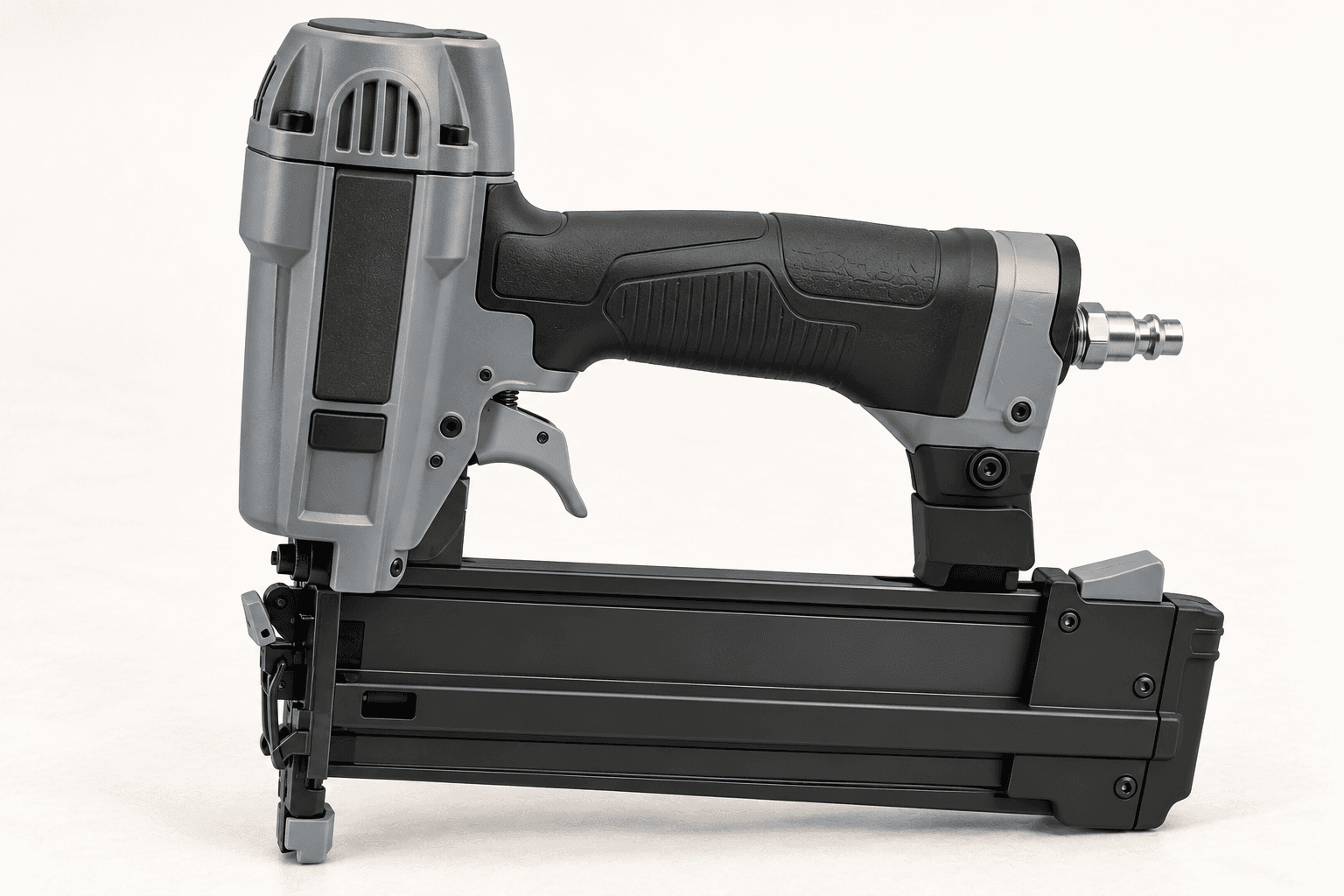
An original educational poster identifies 10 documented construction features. The numbered descriptions remain readable below the artwork on narrow screens.
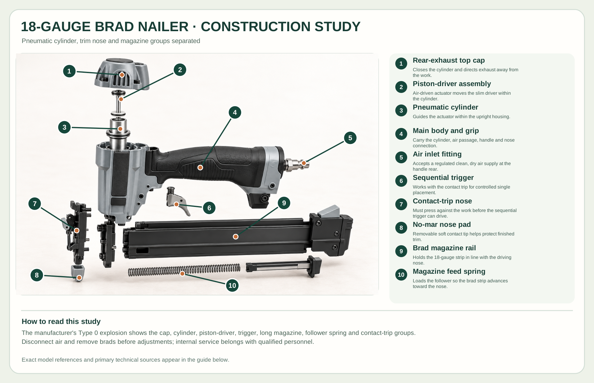
Closes the cylinder and directs exhaust away from the work.
Air-driven actuator moves the slim driver within the cylinder.
Guides the actuator within the upright housing.
Carry the cylinder, air passage, handle and nose connection.
Accepts a regulated clean, dry air supply at the handle rear.
Works with the contact trip for controlled single placement.
Must press against the work before the sequential trigger can drive.
Removable soft contact tip helps protect finished trim.
Holds the 18-gauge strip in line with the driving nose.
Loads the follower so the brad strip advances toward the nose.
Technical references: DeWalt DWFP12231 official product page · DeWalt DWFP12231 Type 0 instruction manual · DeWalt DWFP12231 Type 0 parts explosion. The pneumatic actuator travels inside the upright cylinder, the sequential trigger and contact trip govern operation, and the magazine feeds 18-gauge brads to the nose. The image is a teaching arrangement of official Type 0 parts, not a repair procedure. Original educational artwork depicts documented component groups and their relationships; it is not a service sequence or a replacement for the exact model manual.
DeWalt's DWFP12231 Type 0 drives 18-gauge brads from 5/8 to 2 inches with a regulated 70–120 PSI air supply. Its straight magazine, sequential trigger, depth wheel, rear exhaust and no-mar tip suit trim and cabinetry placement. Brads help hold a fitted assembly while adhesive cures; they are not a substitute for a specified structural joint or structural fastener.
Compressed air enters the rear handle fitting. With the contact trip pressed and the sequential trigger actuated in the order specified by the manual, air drives a piston-driver down the cylinder to place one brad. The magazine spring and follower feed the next fastener to the nose. The drawing separates documented Type 0 groups for explanation, not for owner service or a firing sequence.
Use clean, dry regulated air at the maker's operating range. The top cap closes and exhausts the cylinder.
The contained driver delivers the brad; internal pneumatic service is for qualified repair rather than routine adjustment.
Trigger and work-contact element are a paired safety system. Never bypass either part.
The rail, follower and spring feed the correct brad strip; the nose and soft pad register on the work.
These decisions make the mechanism useful at the bench.
Choose specified 18-gauge brads of suitable length for the trim and substrate; inspect for hidden services.
Regulate within 70–120 PSI, then adjust the tool's depth on scrap so heads sit as intended without crushing the face.
Seat the no-mar tip on supported stock and follow the manual's sequential actuation order.
Use small brads to hold fitted moulding while the adhesive cures, with a backing surface behind the piece.
Pin nonstructural components after checking alignment and using the joint method required by the project.
Hold a strip in place without replacing clamps or structural connectors where required.
Use the steps for a first pass, then inspect the work before changing the setup.
Supply pressure moves the driver; the depth wheel fine-tunes the result within the maker's range.
Knots, hard grain and angle can redirect a thin fastener; keep hands away from the possible exit path.
The work-contact element and trigger must function as supplied. Do not tie down or defeat them.
This model needs an air hose; battery tools trade the hose for greater mass and charging needs.
18-gauge brads leave smaller holes but offer less holding power than larger finish nails.
Select length to avoid blow-through and hidden utilities while reaching sound backing.
Stop the tool and disconnect power before investigating a fault or changing a part.
Test depth wheel, pressure within range, brad length and backing on scrap.
Disconnect air, unload, open the jam latch per the manual and inspect compatible brads and rail cleanliness.
Disconnect and check hose, fitting and regulated supply; refer internal seal faults to qualified service.
Use the exact tool manual for setup, limits and replacement parts. These lessons, documents and model pages teach relevant techniques or help compare real variations.
These maker-owned links document relevant tools and tool brands. A product brand may use another company's factory; compare the exact model before choosing parts or accessories.
Cutters, abrasives, guards, guides, dust fittings and service parts vary by tool. Check the model plate and manufacturer manual before ordering or changing a component.
Compare the Joinery family →Continue through the Tools library