
Rail and fixed jaw
The profiled steel rail resists twist. A fixed cast jaw terminates one end and gives the opposing clamping face.
Hold a joint under steady pressure with a sliding cast jaw and a controlled screw rather than extra force.
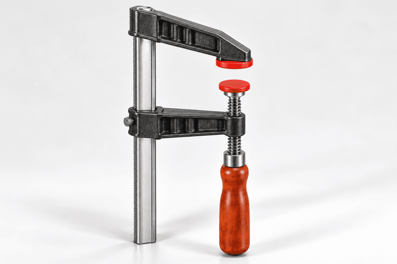
An original educational poster identifies 7 documented construction features. The numbered descriptions remain readable below the artwork on narrow screens.
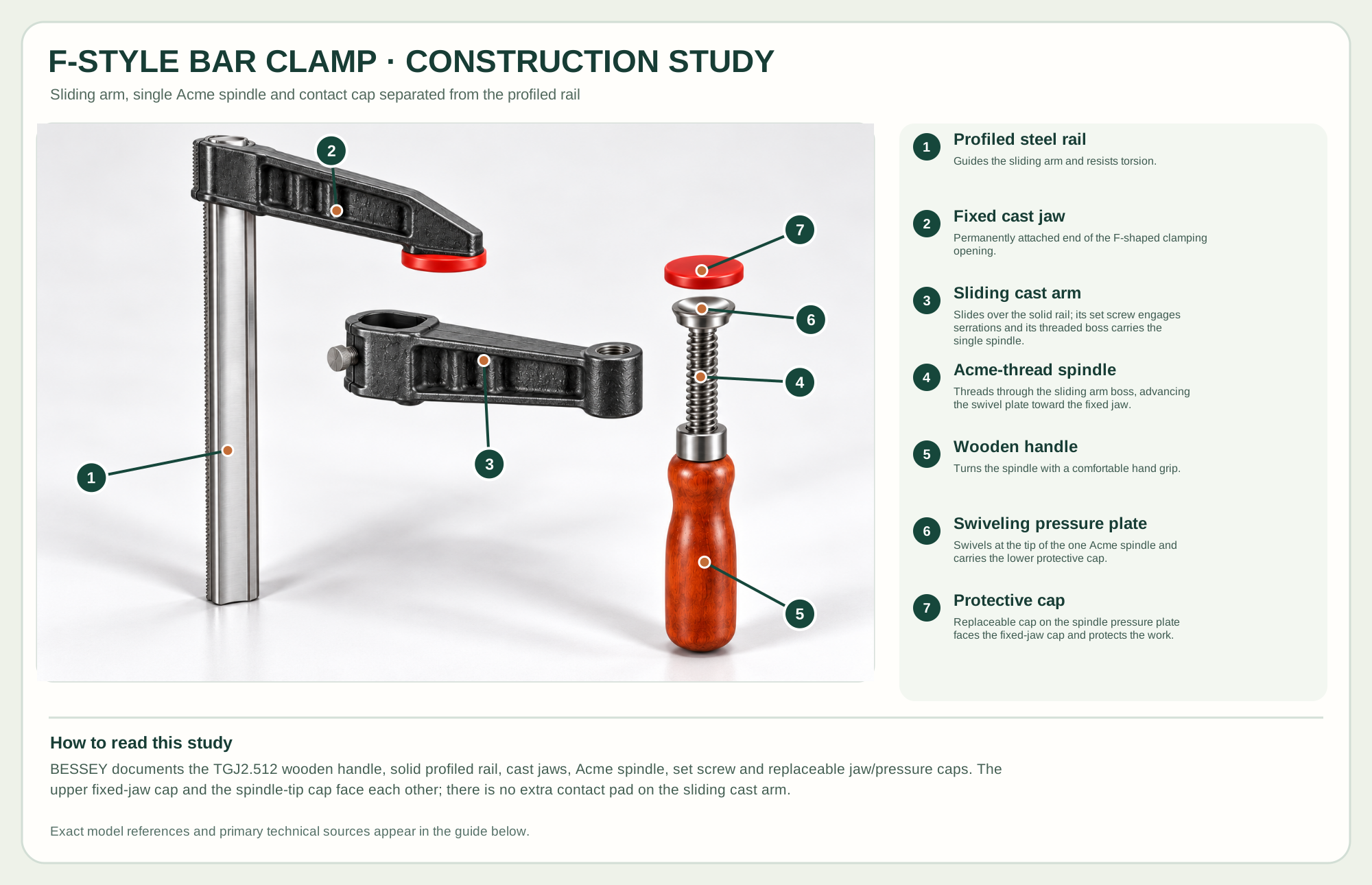
Guides the sliding arm and resists torsion.
Permanently attached end of the F-shaped clamping opening.
Slides over the solid rail; its set screw engages serrations and its threaded boss carries the single spindle.
Threads through the sliding arm boss, advancing the swivel plate toward the fixed jaw.
Turns the spindle with a comfortable hand grip.
Swivels at the tip of the one Acme spindle and carries the lower protective cap.
Replaceable cap on the spindle pressure plate faces the fixed-jaw cap and protects the work.
Technical references: BESSEY Woodworking Clamps catalog · BESSEY Accessories and Spare Parts · BESSEY 2025 catalog: fixed jaw and swivel pressure cap set for TGJ2.5. The fixed upper jaw remains attached to the solid profiled rail. The lower arm slides onto that rail and its set screw engages serrations; a single Acme spindle passes through the arm's threaded boss so the swivel pressure plate and protective cap face the fixed jaw. The separation shows physical relationships, not a required user disassembly sequence. Original educational artwork depicts documented component groups and their relationships; it is not a service sequence or a replacement for the exact model manual.
BESSEY's TGJ2.512 has a 12-inch clamping capacity, 2½-inch throat and listed 600-pound maximum clamping force. Its profiled steel rail carries a fixed malleable-cast jaw and a sliding cast arm. A wooden handle turns an Acme-thread spindle with a swiveling pressure plate. The brand-neutral illustration retains this real geometry without promoting a color or logo. Parallel-jaw clamps suit broad flat panels; an F-clamp is lighter and reaches around many general joinery setups.
Slide the movable arm along the rail until the pads straddle the work. The arm's anti-slip system engages the rail serration; turning the wooden handle advances the Acme spindle so the swiveling pressure plate bears against the work toward the fixed jaw. The study removes the arm from the rail and separates spindle, plate and cap as documented replacement groups. The fixed jaw remains attached to the rail.
The profiled steel rail resists twist. A fixed cast jaw terminates one end and gives the opposing clamping face.
Cast arm travels on the rail to match stock width; its anti-slip engagement helps it hold position under load.
Acme thread converts handle rotation into axial force; turn smoothly and stop when the joint seats.
The swivel plate bears on stock; documented replaceable caps protect surfaces but may still mark soft or finished wood.
These decisions make the mechanism useful at the bench.
Dry-fit a joint, position pads over solid bearing surfaces and use cauls when pressure must spread.
Move it close to the work with the spindle backed off; check both pads contact squarely.
Turn the handle only until the joint closes and remains aligned. More force can bow a panel or crush fibers.
Pair clamps across rails and check diagonals while adhesive remains open.
Fix a fence or stop to a bench with pads that do not obstruct the cut.
Use distributed clamps and cauls to keep narrow boards aligned during a dry fit or glue-up.
Use the steps for a first pass, then inspect the work before changing the setup.
The sliding jaw sets the rough span; the spindle creates the final pressure. They are separate real mechanisms.
A caul or block spreads load across delicate stock and keeps a pad off a finished edge.
A joint needs adequate even contact. Excess force squeezes a glue line dry or distorts work.
BESSEY lists several TGJ lengths; choose opening and reach for the actual assembly.
Wooden and composite handles are offered on related TG clamps; the reference TGJ2.512 uses wood.
F-style, parallel and one-hand trigger clamps solve different workholding needs; compare usable reach and pad shape.
Secure the work, protect sharp edges and release any stored clamping pressure before adjustment or maintenance.
Inspect rail serration and anti-slip engagement; clean contamination and replace a damaged arm.
Reduce force, move pressure nearer the joint and add cauls or a balanced opposing clamp.
Fit a sound cap and a wider sacrificial block before retightening.
Use the exact model documentation for setup, limits and replacement parts. These lessons, documents and model pages teach relevant techniques or help compare real variations.
Official TGJ2.512 capacity, throat, rail, jaws, spindle and anti-slip system.
Official pressure plate, cap and sliding-arm replacement groups; used to limit illustrated separations.
These maker-owned links document relevant tools and tool brands. A product brand may use another company's factory; compare the exact model before choosing parts or accessories.
Handles, irons, saw plates, clamping pads and other replacements vary by maker and model. Use the maker's documentation before changing a component.
Compare the Woodworking Clamps family →Continue through the Tools library