
Guide block and bushings
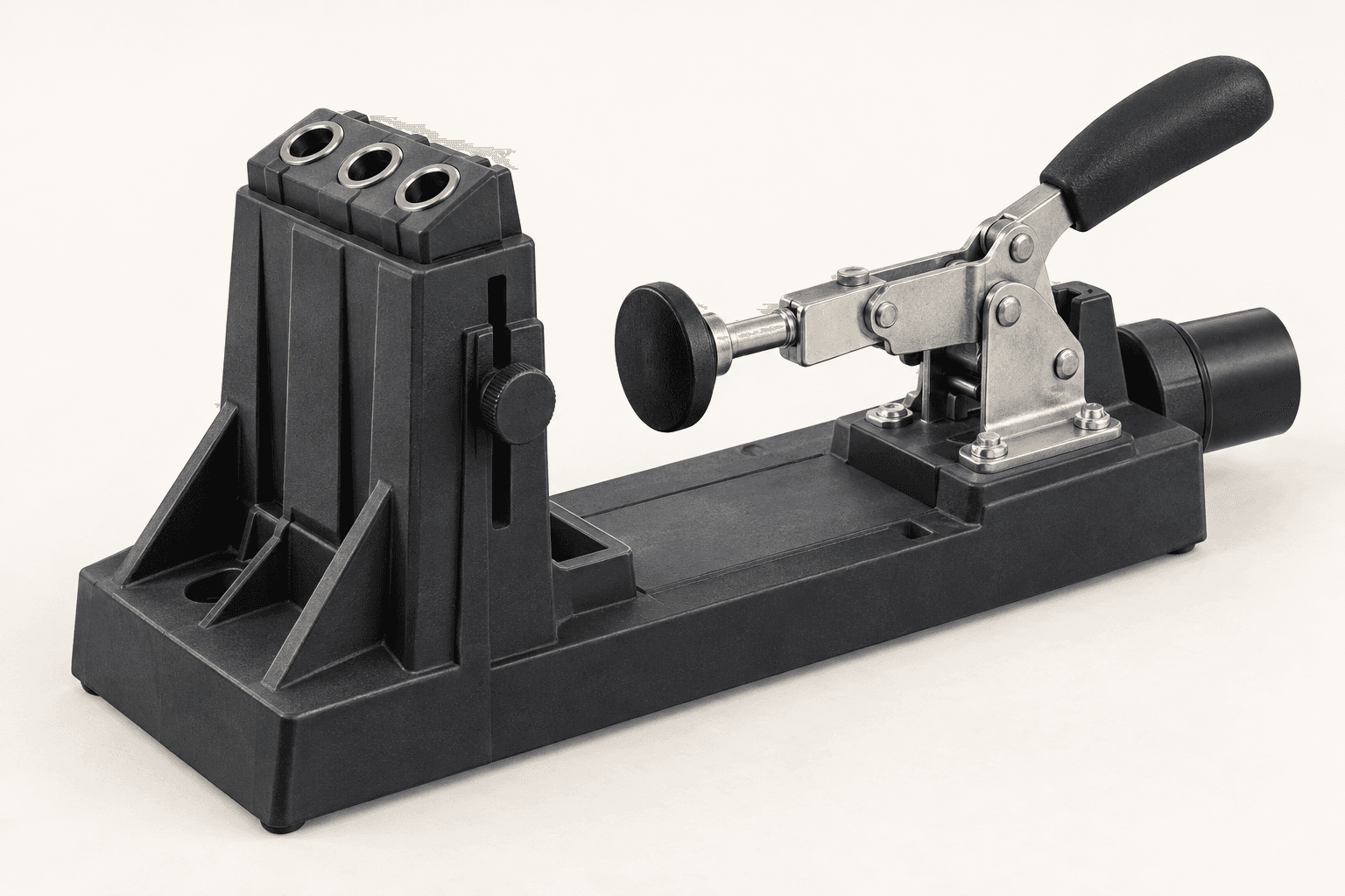
The K4's removable block has three fixed hardened guide holes. The holes are part of the block, not three loose interchangeable sleeves.
Set the drilling guide, clamp the stock and choose the screw for a clean, repeatable hidden joint.
An original educational poster identifies 8 documented construction features. The numbered descriptions remain readable below the artwork on narrow screens.
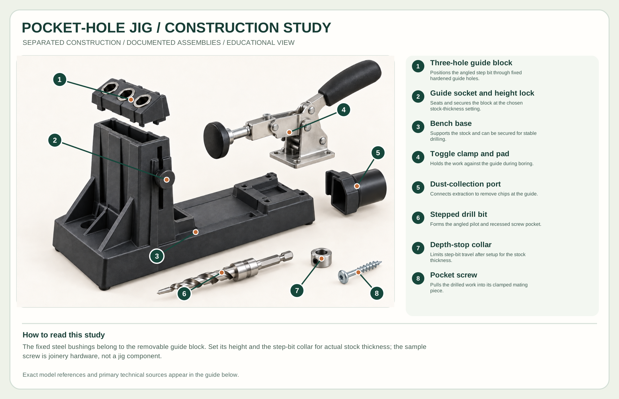
Positions the angled step bit through fixed hardened guide holes.
Seats and secures the block at the chosen stock-thickness setting.
Supports the stock and can be secured for stable drilling.
Holds the work against the guide during boring.
Connects extraction to remove chips at the guide.
Forms the angled pilot and recessed screw pocket.
Limits step-bit travel after setup for the stock thickness.
Pulls the drilled work into its clamped mating piece.
Technical references: Kreg K4 owner's manual · Kreg K4 product details · Kreg screw selection lesson. The removable three-hole guide, bench base, toggle clamp, vacuum port and drill hardware are physically separated to explain their roles. This brand-neutral arrangement teaches documented exterior components, not a K4 service sequence. Original educational artwork depicts documented component groups and their relationships; it is not a service sequence or a replacement for the exact model manual.
A pocket-hole jig locates an angled stepped hole so a pocket screw can draw two boards together. It is quick for face frames, cabinets and shop fixtures, but screw placement, grain, stock thickness and visible-pocket placement limit where it is appropriate. The Kreg K4 is the reference for this construction study; the neutral artwork explains its exterior assemblies rather than an exact service sequence.
A removable guide block with hardened steel guide holes positions a stepped drill bit. A stop collar limits its travel. The toggle clamp presses the work against the guide, while a compatible pocket screw is driven through the pocket into the mating part. Clamp the joint during assembly so the screw cannot shift the pieces.
The K4's removable block has three fixed hardened guide holes. The holes are part of the block, not three loose interchangeable sleeves.
Set the guide height for the actual material thickness and secure it before drilling. Test a scrap pair when the stock is nonstandard.
The over-center lever moves a pressure pad against the work. Adjust it to hold firmly without crushing the stock.
The pilot and larger shoulder form the screw path and recessed pocket. The collar establishes drill depth using the K4's setting method.
The base supports work and can be secured to a bench. A removable dust port helps clear chips when connected to suitable extraction.
These decisions make the mechanism useful at the bench.
Measure actual thickness, position the guide block, then set the stop collar according to the K4 instructions. A nominal board size can differ from its real thickness.
Secure the base and work. Seat the piece against the guide and adjust the clamp pad before starting the drill.
Match screw length and thread to the stock thickness and material using the maker's chart. A test joint checks both penetration and splitting.
Pocket screws pull rails to stiles quickly when the frame is clamped flat and the pockets can face the hidden side.
Use pockets on suitable frame or carcass parts while planning load direction, appearance and access for the driver.
The removable guide can serve a compatible portable setup; support and clamp it according to the maker's instructions.
Use the steps for a first pass, then inspect the work before changing the setup.
A mis-set collar can make a shallow pilot or drill through the work. Match both guide height and collar position to the same stock thickness.
Coarse and fine pocket screws suit different materials; screw length also changes with thickness. Use Kreg's current selection chart rather than a universal guess.
Visible pockets, thin edges, unsupported cross-grain or highly stressed connections may call for another joint or reinforcement.
A bench jig gives repeatable clamping; smaller portable guides trade speed for access to assembled work.
Different guide systems and bit/screw sets serve thin or thick stock; do not mix their depth charts or hardware.
Choose guide-hole locations to keep screws away from edges and from each other. Narrow pieces may use fewer holes.
Secure the work, protect sharp edges and release any stored clamping pressure before adjustment or maintenance.
Stop and check measured thickness, guide height, collar setting and screw length on scrap.
Clamp the mating faces, check pocket location and drive gradually.
Clear chips and inspect the stepped bit, guide alignment and drill speed.
Use the exact model documentation for setup, limits and replacement parts. These lessons, documents and model pages teach relevant techniques or help compare real variations.
Kreg's illustrated setup and drilling lesson.
Maker videos on setup and pocket-hole techniques.
Maker guidance for screw length and thread by stock and material.
Official documented capacity and removable guide details.
These maker-owned links document relevant tools and tool brands. A product brand may use another company's factory; compare the exact model before choosing parts or accessories.
Handles, irons, saw plates, clamping pads and other replacements vary by maker and model. Use the maker's documentation before changing a component.
Compare the Joinery family →Continue through the Tools library