
Straightedge
Use a trustworthy reference edge to find gaps and high areas, then check enough positions to understand the surface rather than trusting a single line.
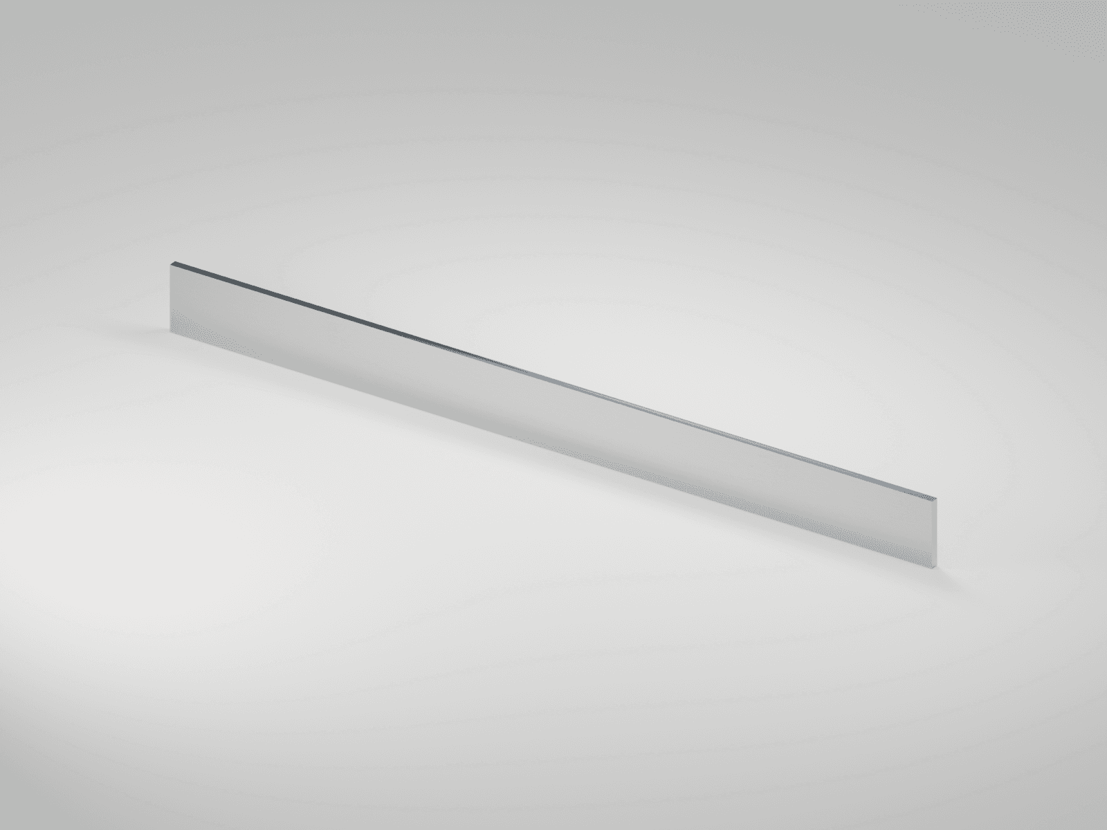
See the intact tool and its features
An original educational poster identifies 4 documented features of this tool. The numbered descriptions remain readable below the artwork on narrow screens.
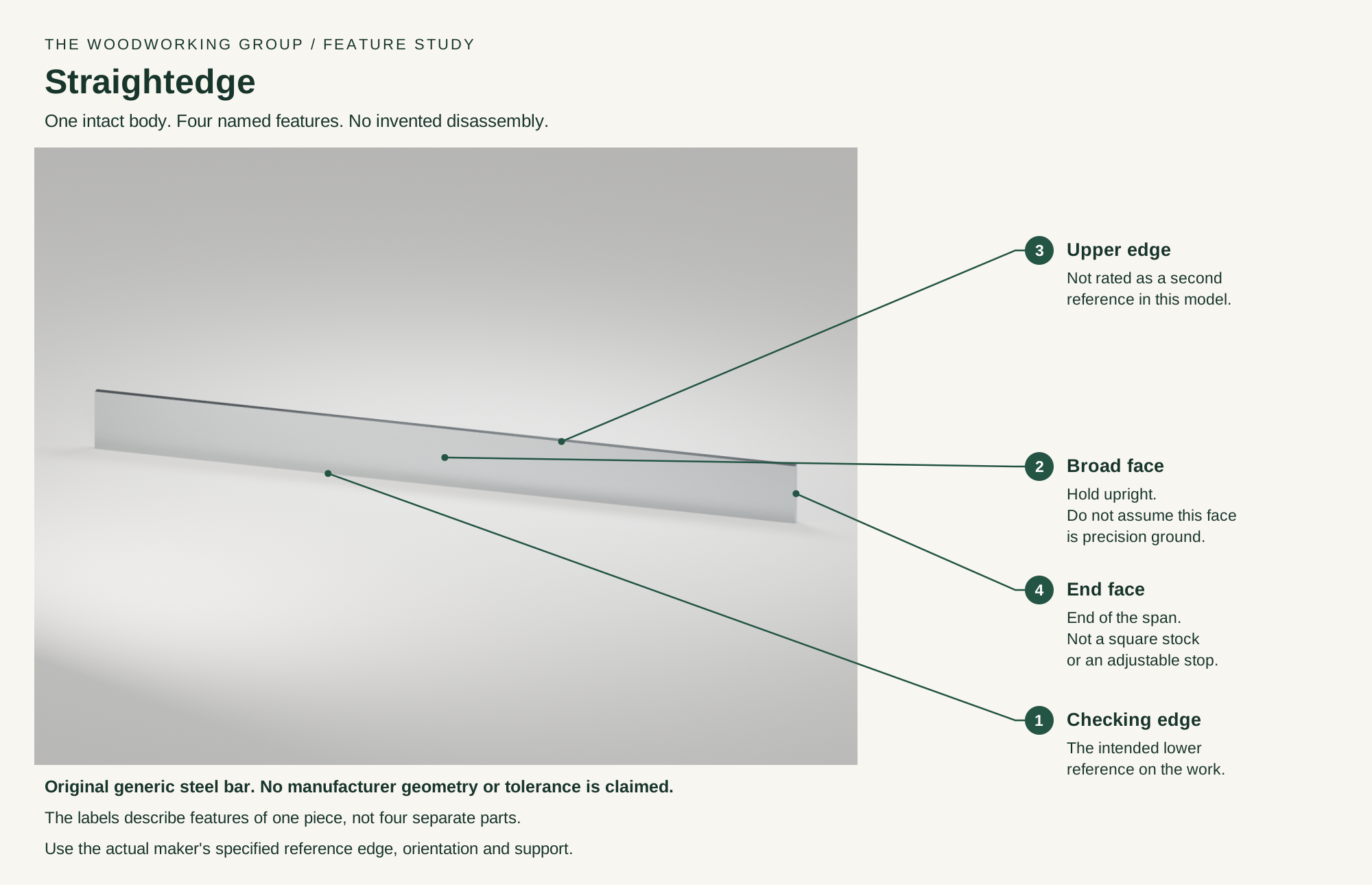
- Checking edge
Intended lower reference placed on the work.
- Broad face
Area for holding the body upright without distorting it.
- Upper edge
Opposite long edge of the same bar.
- End face
End of the usable span.
Technical references: Starrett square-edged steel straightedge · Calibrating your workshop · A precision notched straightedge. Both studio views use the same original 24 by 1/4 by 2 inch rectangular mesh; only the camera changes. Dimensions and finish are illustration choices, not a maker specification or tolerance. Only the lower edge is identified as the intended checking reference. No certification is implied for the other edges, face or end. Original educational artwork depicts the intact tool and magnified features; the additional views are not detachable parts.
What it is and what each part does
A straightedge compares a surface with a straight reference along the line it touches. A rule primarily measures length; a spirit level references gravity; a square checks an angle. Winding sticks compare transverse slopes for twist. None of those jobs is automatically covered by a straight-looking bar.
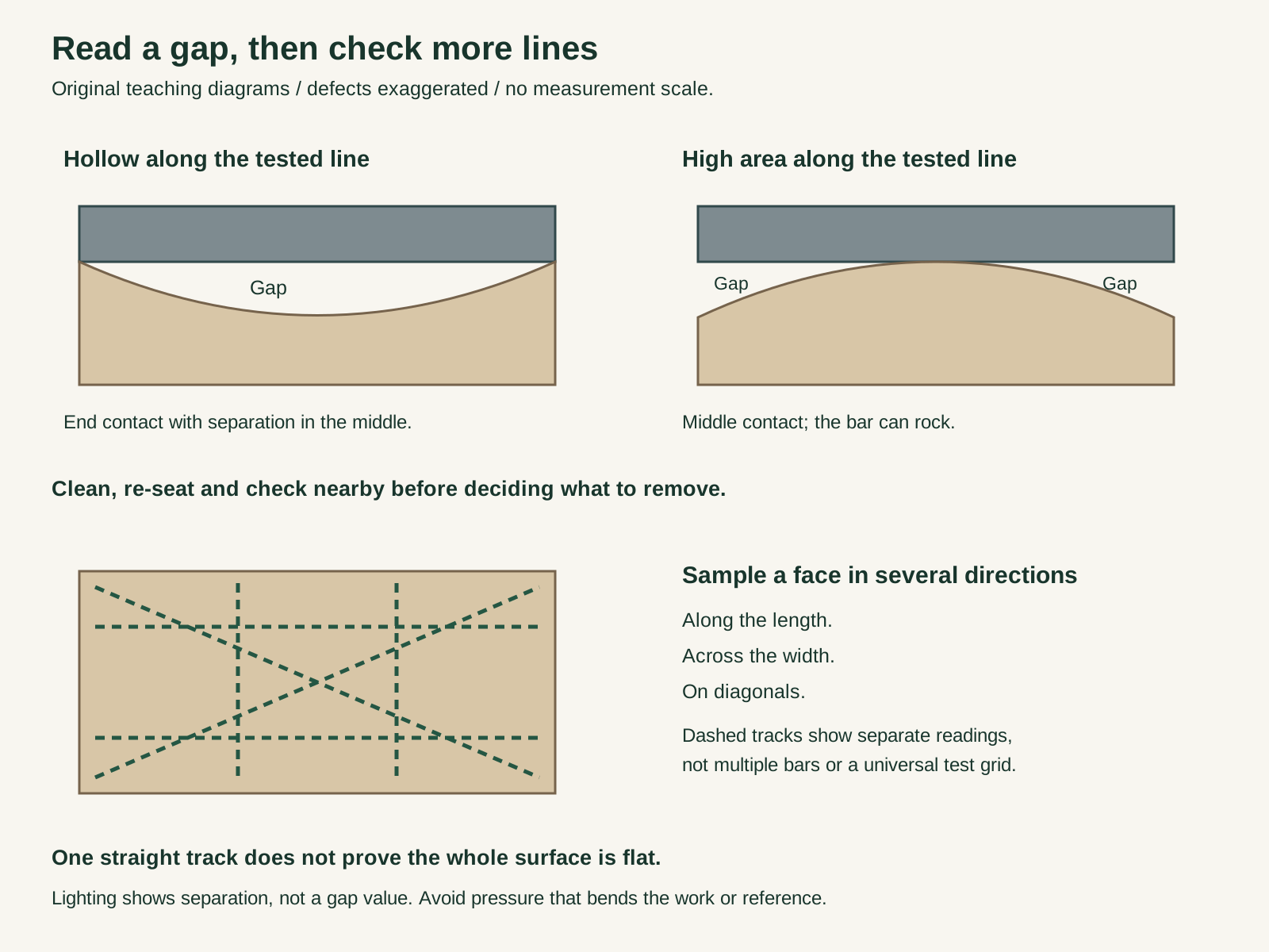
Place the intended checking edge gently on a clean, supported surface and look at the contact line with light behind it. A gap shows separation from that reference. Contact at the ends with a middle gap suggests a hollow along that line; rocking over a middle contact suggests a high area. Re-seat and test nearby lines before concluding that the work, rather than debris, support or the tool, is responsible. One clear line does not certify the entire face flat.
1. Checking edge
The intended narrow reference contacts the work. Use the edge specified by the maker; do not assume every edge or face has the same accuracy.
2. Broad face
Provides an area to hold the bar and keep it upright. It is not automatically a calibrated flat surface or a reference for a 90-degree angle.
3. Upper edge
The opposite long edge belongs to the same body. This generic drawing does not certify it as a second checking edge.
4. End face
Marks the end of the available span. The short end is not a square stock, a stop or a separately adjustable part.
How the main groups connect
Set, guide and control the action
These decisions make the mechanism useful at the bench.
Use a known reference
Inspect the checking edge for corrosion, nicks and contamination. Use a tool with a stated tolerance appropriate to the job, not an unchecked offcut or flexible rule.
Support without forcing
Support the work stably without clamping it into an artificially flat shape. Follow any tool-specific orientation and support instructions, especially for long straightedges.
Use gentle contact
Hold the bar upright without bending it or pressing the work down. Keep it from toppling; apparent gaps can change when the tool is tipped.
Check a prepared board edge
Look along the full intended joint line. Move the reference to investigate local hollows and high areas; do not average them away with pressure.
Assess a face
Check several lines along the length, across the width and on diagonals. Combine the evidence with winding sticks when diagnosing twist.
Track hand-planing progress
Set the plane aside, remove shavings and repeat the same checks. Record verified areas needing attention instead of guessing from a single bright gap.
Setup, technique and finish quality
Use the steps for a first pass, then inspect the work before changing the setup.
- Choose a straightedge long enough for the span and accurate enough for the intended work. Read its edge, orientation and support requirements.
- Inspect and clean the reference and work. Arrange stable support; do not flatten flexible stock with clamps just for the reading.
- Set the intended edge on the work and hold the body upright with light contact. Keep cutting tools clear.
- Use a light source behind the contact line. Look for where the edge touches, where light passes and whether the bar rocks.
- Re-seat the bar and repeat nearby. Check along, across and diagonally over a face; a shorter tool checks only its present span.
- If a gap size matters, use a suitable clean feeler gauge gently without lifting or tilting the straightedge. A visible light line alone is not a numerical measurement.
- Mark only verified findings. Remove the straightedge before cutting, then clean and repeat after each correction.
A line is not a whole plane
One straight track can exist on a cupped, twisted or otherwise uneven face. Sampling in several directions is evidence, not a formal calibration certificate.
Light shows a gap, not its size
Brightness depends on lighting and viewpoint. Use a feeler gauge when a gap value is needed; do not force the blade or treat glare as a ruler.
The reference can be wrong
Dirt, damage, bending and unsuitable support can imitate surface error. Reversing the bar can reveal inconsistent readings but cannot by itself certify accuracy.
One body, four features
The numbered view identifies regions of one intact bar. There are no joints, fasteners, internal mechanisms or removable parts to invent.
What changes by model or material
A rectangular steel bar can provide a durable reference, but its rated edges, tolerance and support instructions depend on the actual tool.
A thinner reading edge can help reveal light gaps. It is more delicate and needs suitable handling; this model is not a beveled design.
Purpose-made profiles reduce weight and may stand more readily on edge. Do not assume an arbitrary extrusion has a precision-machined reference.
Choosing the tool
- Match the usable length to the surface or joint you need to check. A short span can miss long, gradual curvature.
- Choose a stated straightness tolerance and usable orientation suitable for the task. A printed scale, shiny finish or material name alone is not proof of accuracy.
- Favor a manageable body with protected storage. For demanding measurements, use a verified reference and a suitable checking procedure.
Useful accessories
- Raking or back lighting for a clear contact line
- Clean feeler gauges for selected gap checks
- Pencil or chalk to record confirmed areas
- Stable supports and a protective sleeve or case
Care, troubleshooting and safety
Secure the work, protect sharp edges and release any stored clamping pressure before adjustment or maintenance.
Care checklist
- Clean and dry the tool after use; protect steel from corrosion as its maker recommends. Avoid transferring oily residue to finishing surfaces.
- Protect the reference edge from drops, abrasive surfaces and other tools. Store it as recommended so it is not bent or damaged.
- Have a suspect precision edge checked or replace it. Do not casually file, sand or stone it and then assume its tolerance is unchanged.
Common mistakes
- Treating one gap-free line as proof that the entire face is flat.
- Pressing the tool or work until the gap disappears.
- Assuming a ruler, level housing or scrap bar has a suitable straightness tolerance.
- Using the precision checking edge as a saw fence, pry bar or everyday cutting guide.
Safety at the operation
- Support heavy stock before checking it; do not let the bar or the work fall onto hands or feet.
- Handle thin metal edges carefully and keep fingers out of cutting paths. A reference bar is not a guard or clamp.
- Remove the straightedge, feeler gauges and loose tools before planing, sawing or starting a machine.
- Machine-table checks require the machine-specific powered-off procedure and isolation from power. This guide does not authorize adjustments, reaching across cutters or removing guards.
When the result goes wrong
Clean and re-seat it, inspect the tool and check the work support. If repeatable, investigate a high area along that line; do not immediately remove the center of the board.
Recheck the contact at the ends and nearby tracks. A hollow is one possible cause; dirt at the contacts or a faulty reference can imitate it.
Reduce pressure, keep the body upright and confirm the work is not flexing. Follow the maker's support instructions for the straightedge.
Check more directions, the mating piece and the supports. Look for twist and defects beyond the tested line or beyond the tool's length.
Manuals and educational resources
Use the exact model documentation for setup, limits and replacement parts. These lessons, documents and model pages teach relevant techniques or help compare real variations.
Manufacturer documentation
Learn and compare
Calibrating your workshop
Derek Jones explains reference checks and careful use of feeler gauges. Plane-specific tolerances in the article are not universal acceptance limits.
A precision notched straightedge
Covington & Sons discusses light-gap checks, reference care and its different beveled, notched design. The TWG model does not depict that product.
General hand-tool operation
CCOHS guidance on inspection, clear work areas and handling tools safely.
Manufacturers & Brands
These maker-owned links document relevant tools and tool brands. A product brand may use another company's factory; compare the exact model before choosing parts or accessories.
Choose parts for the exact model
Handles, irons, saw plates, clamping pads and other replacements vary by maker and model. Use the maker's documentation before changing a component.
Compare the Layout Tools family →Continue through the Tools library