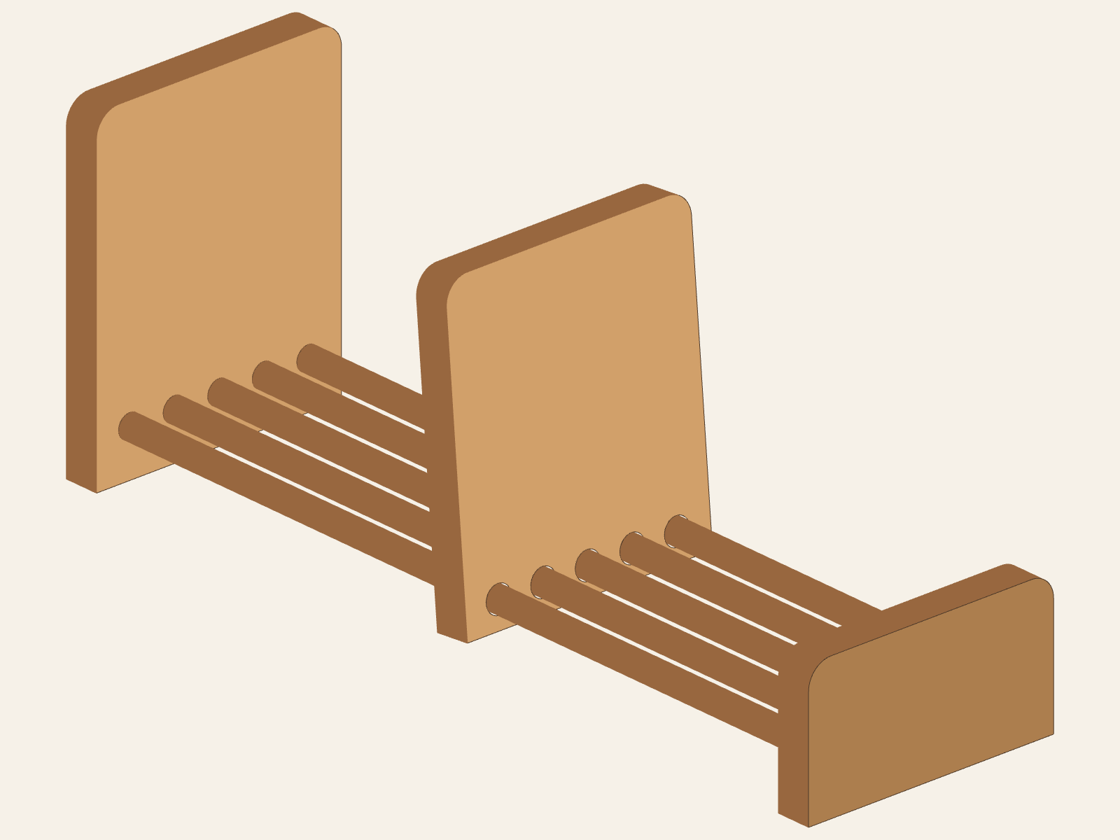
How the rack works
Five straight D dowels run between the fixed A and B ends. The third board, C, passes over those rods and remains unglued so it can be adjusted. This lesson helps a learner recognize the parts, compare prepared holes with Purdue's drawing, and observe an adult-checked dry-fit.
Know the four part marks
- A · Large fixed end
- One board, ¾ × 5½ × 7 in.
- B · Small fixed end
- One board, ¾ × 5½ × 3 in.
- C · Adjustable end
- One board, ¾ × 5½ × 6½ in, with five larger angled through-holes.
- D · Dowels
- Five straight rods, each ½ in diameter × 18 in long.
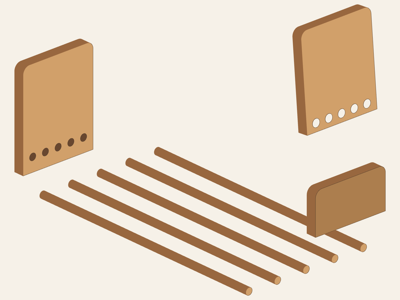
The letter markers identify the separated pieces. A and B each have five fixed blind sockets; C has five through-holes. The next view turns B toward you to show the socket face hidden in the parts picture.
Prepare with an adult
Adult-controlled: measure and cut stock; lay out and drill every blind or angled hole; control the rasp, clamping, glue-up, and finish; check parts and product directions. The Stage 2 badge is a learning pathway, not permission to use a drill, rasp, clamp, adhesive, or finish.
Your check: identify A, B, C, and D after preparation. Compare their marks and holes with Purdue's drawing. Try an unfastened, no-force dry-fit only after the adult confirms the actual parts are ready. Stop if a dowel does not align or a part needs force.
Follow the seven plan steps
Cut the listed stock
The adult measures, cuts, and checks A, B, C, and five D dowels to the finished dimensions above. A learner can match the prepared parts to their marks.
Make the fixed sockets in A and B
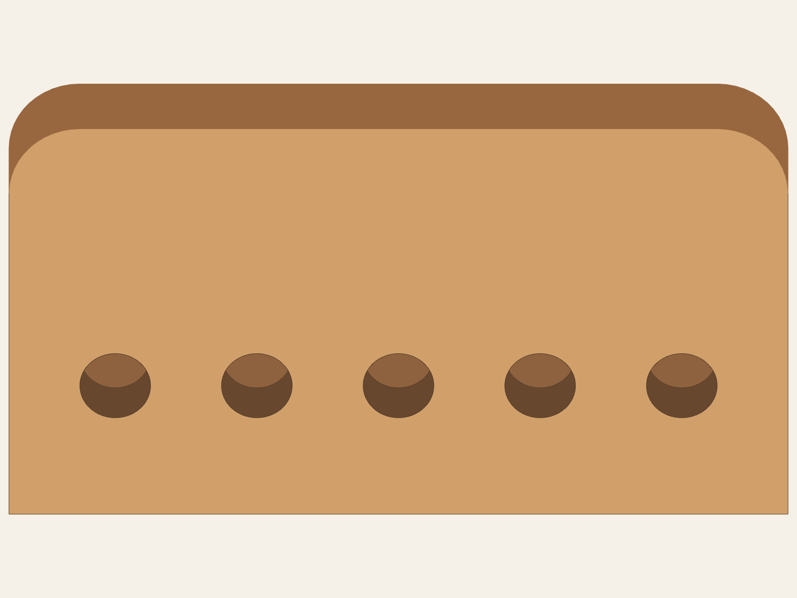
Purdue calls for five ½ in diameter holes, ½ in deep, in each fixed end. The adult lays out and drills these blind sockets. The first section exposes the blind floor; the next shows one D dowel seated to it. Depth is measured along the rod from the opening to the floor.

Before a dowel enters the fixed socketThe open A section shows a blind floor ½ in behind a ½-in-diameter opening. B has the same source-stated hole size and depth; the adjacent section shows a D dowel seated to that floor. 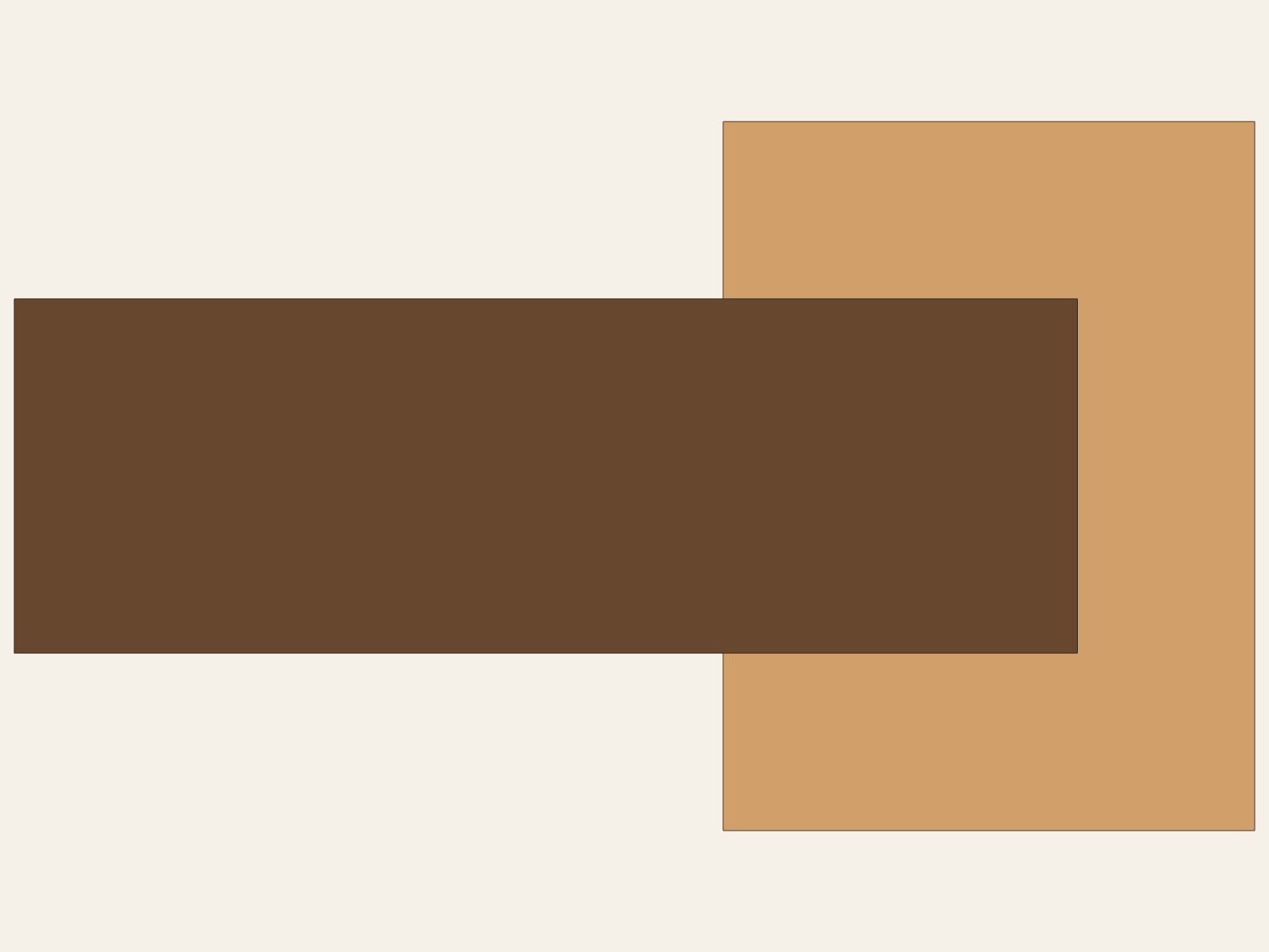
A/B fixed blind-socket sectionSection through one ½-in-diameter × ½-in-deep fixed socket and a D dowel seated to its blind floor. The source does not dimension the first-hole edge offset; the model centers the five-hole row. Make the angled through-holes in C
The adult uses the plan's T-bevel and drill direction to make five 9/16 in through-holes. In the model, the hole and straight D dowel share a horizontal axis. The angle reference is a line perpendicular to C's tilted broad face: that face-normal line and the dowel axis differ by 5°. The board's selected lean direction lets those axes meet; Purdue does not specify its handedness.
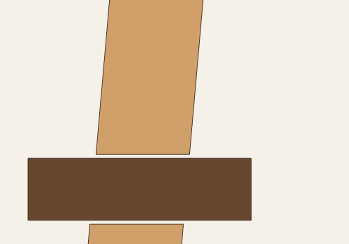
Closer look at one C boreUniform enlargement of the same C section. The dark ½ in D dowel crosses a 9/16 in through-hole, leaving a modeled 1/16 in diameter difference. The whole section is beside it for context; clearance in a drawing is not a physical fit test. 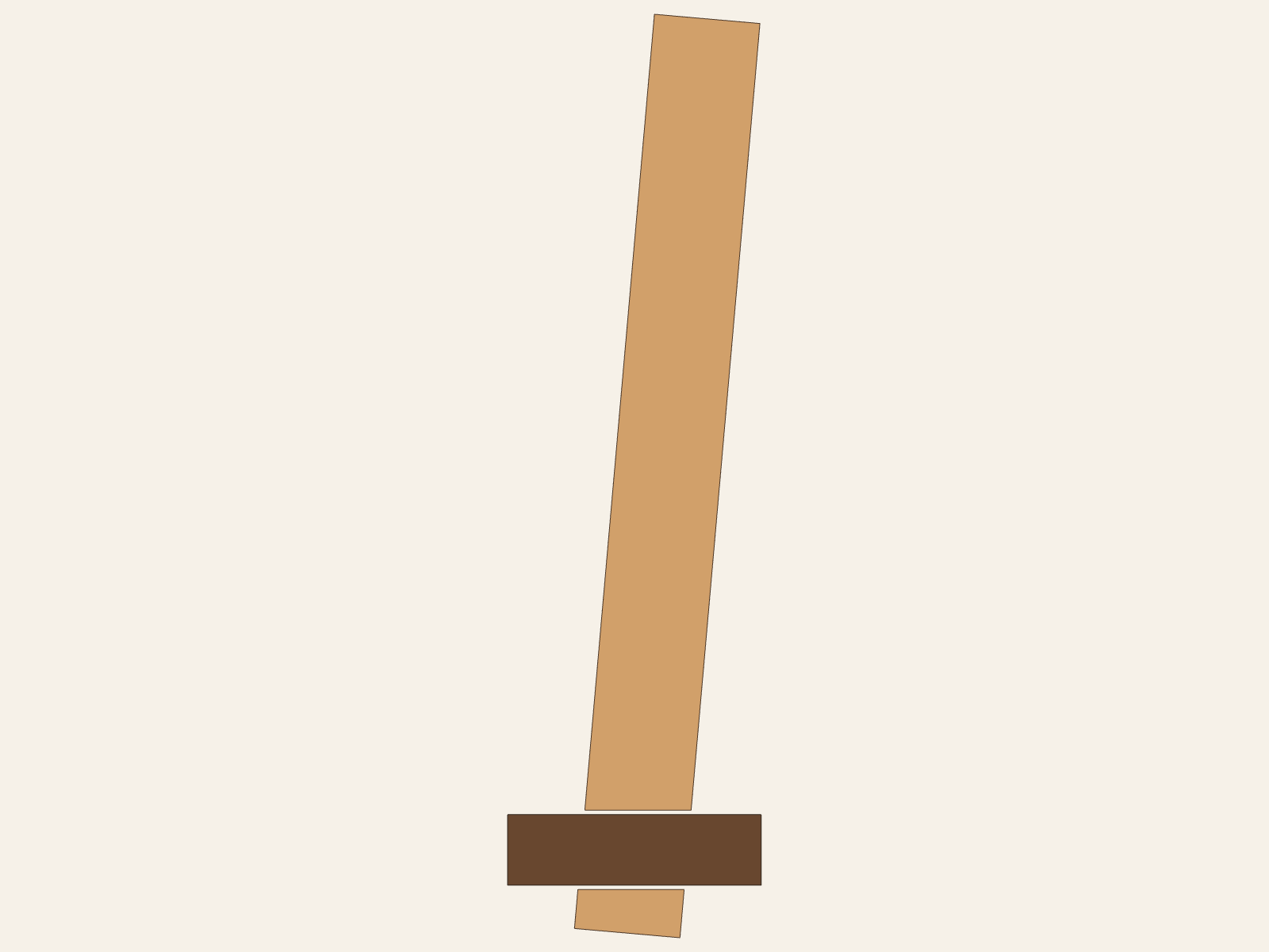
C adjustable through-bore sectionThe model keeps C's 9/16-in through-hole axis aligned to the straight D dowel while C's board face is at the source 5° angle. C stays a separate sliding end; it is not glued in this model. Angle reference in the section above: brown is the straight D dowel and matching bore axis; teal is perpendicular to C's tilted broad face. The angle between those axes is 5°. The enlarged image retains the modeled hole and rod diameter difference.
Round the edges
Purdue names a rasp and sandpaper. The adult controls shaping. A mentor may separately release supported hand-sanding of safe edges after checking the part and setup; no rasp use is released here.
Sand the parts; leave D ends unsanded
The source specifically says not to sand the ends of dowels D. The adult controls sanding and checks those ends. Keep any released hand-sanding task away from them.
Assemble and clamp—keep glue off C
Purdue says to assemble with glue and clamp securely, and warns not to get glue on C. The adult controls all glue and clamping. The three views below give a TWG teaching sequence derived from that construction; Purdue does not supply this detailed order. It keeps C on the rods before the second fixed end closes, so C is never shown entering after both ends are fixed.
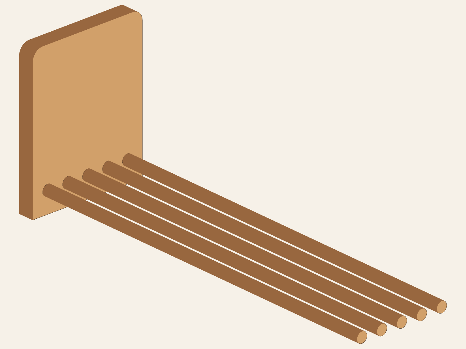
Align five D dowels with AThe five straight rods meet A's fixed socket row. B and C are omitted at this teaching stage; rod lengths and A geometry are unchanged. 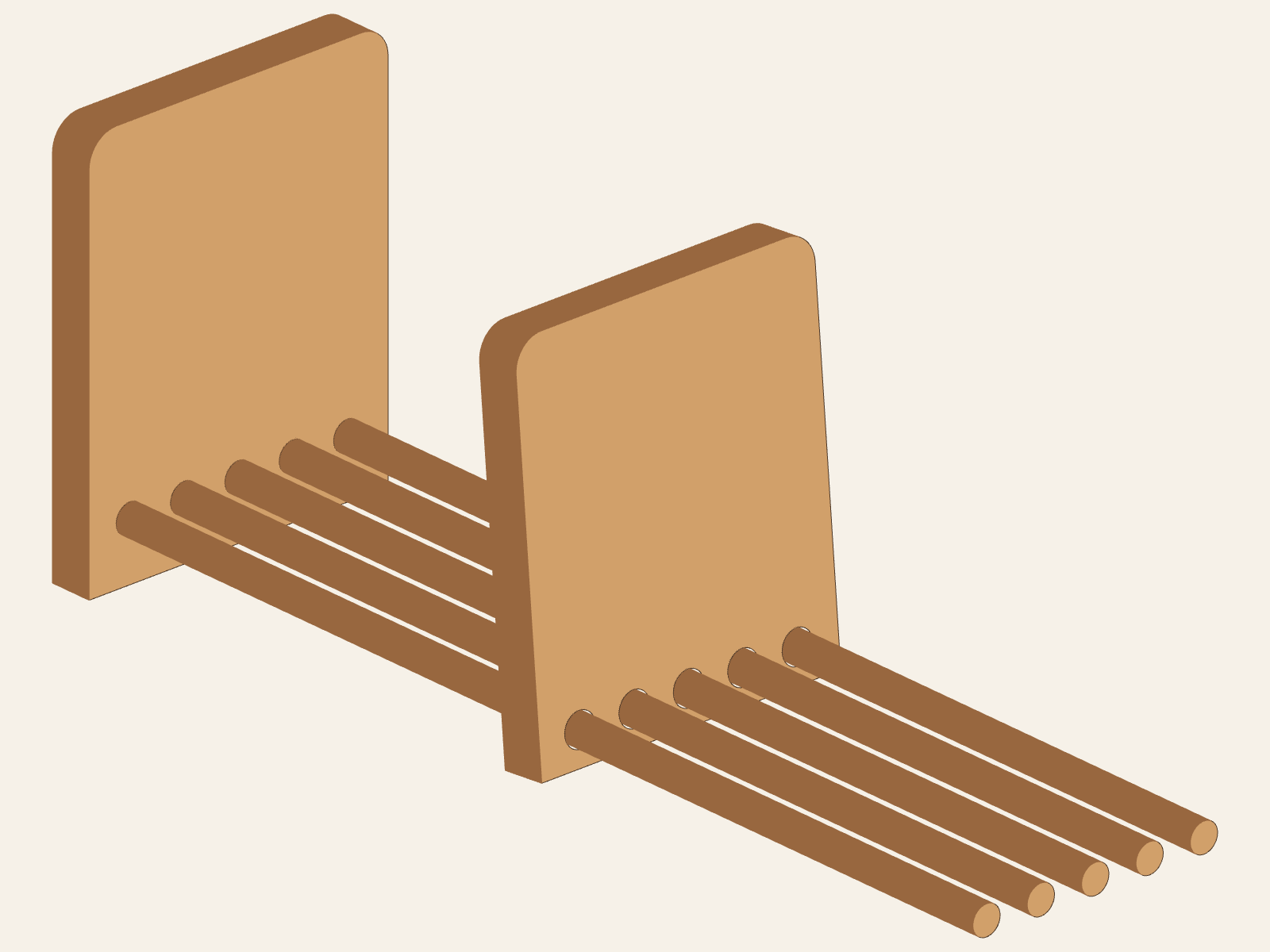
Place unglued C on the rodsC passes over all five rods before B is fixed. The 5° board lean and angled bores align with the same straight dowels; C receives no glue. 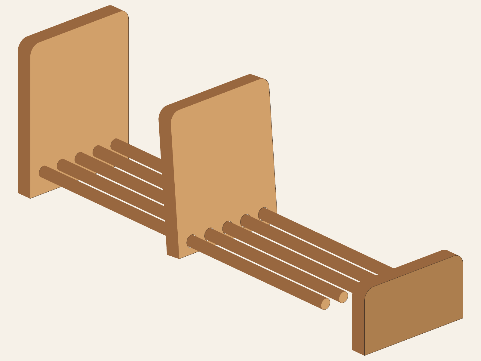
Bring B to the five rod endsB is shown translated away from its final position so its closing relationship is visible. The adult aligns its five fixed sockets and completes the source's glue-and-clamp step without glue on C. After the adult closes B, the same eight parts form the finished arrangement in the page image above. Do not glue C. A learner may identify each stage or compare an unfastened arrangement under adult direction; do not glue, clamp, or force parts.
Two illustrated C positions
These positions reuse the same model geometry. They show where C can be pictured on the rods, without establishing adjustment force, grip, or load capacity.
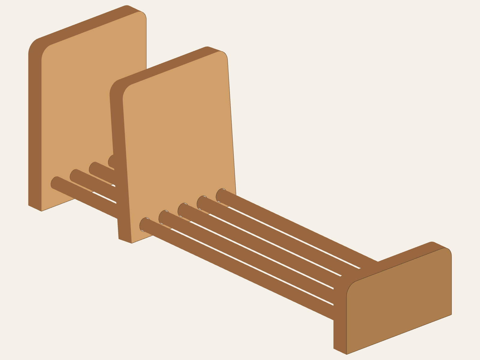
Selected C position · 4½ inOne selected C location measured from A's inner face. This is a geometry example on the same five rods, not evidence of physical adjustment ease or holding force. 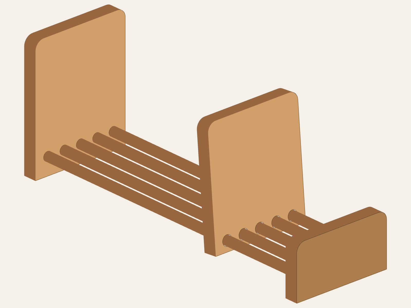
Selected C position · 11½ inA second selected C location measured from A's inner face. All other part geometry stays unchanged; no load or performance result is implied. Apply the chosen finish
The adult selects and applies a finish under its current product directions. Handling dryness alone does not establish readiness for the rack's intended use.
Final inspection and readiness
An adult checks the actual parts, socket seating, C's unglued movement, edges, alignment, glue placement, and finish against the plan and the selected products' requirements for intended use. A learner can point out visible gaps, binding, or rough areas and ask the adult to assess them. Do not force C or assume the model proves strength, stability, a safe load, or service readiness.
Read the original plan
Open Purdue plan · printed page 4
Source: Purdue 4-H, Woodworking Plans — Making the Cut, Level 2, “Adjustable Book Rack,” printed page 4. Purdue supplies the dimensions, hole callouts, seven steps, and no-glue-on-C instruction. TWG selected the centered hole row, corner radius, C lean direction and display positions, and the illustrated assembly order where the source is silent. The views explain construction relationships; no physical fit or use testing, final visual approval, or owner approval is established.