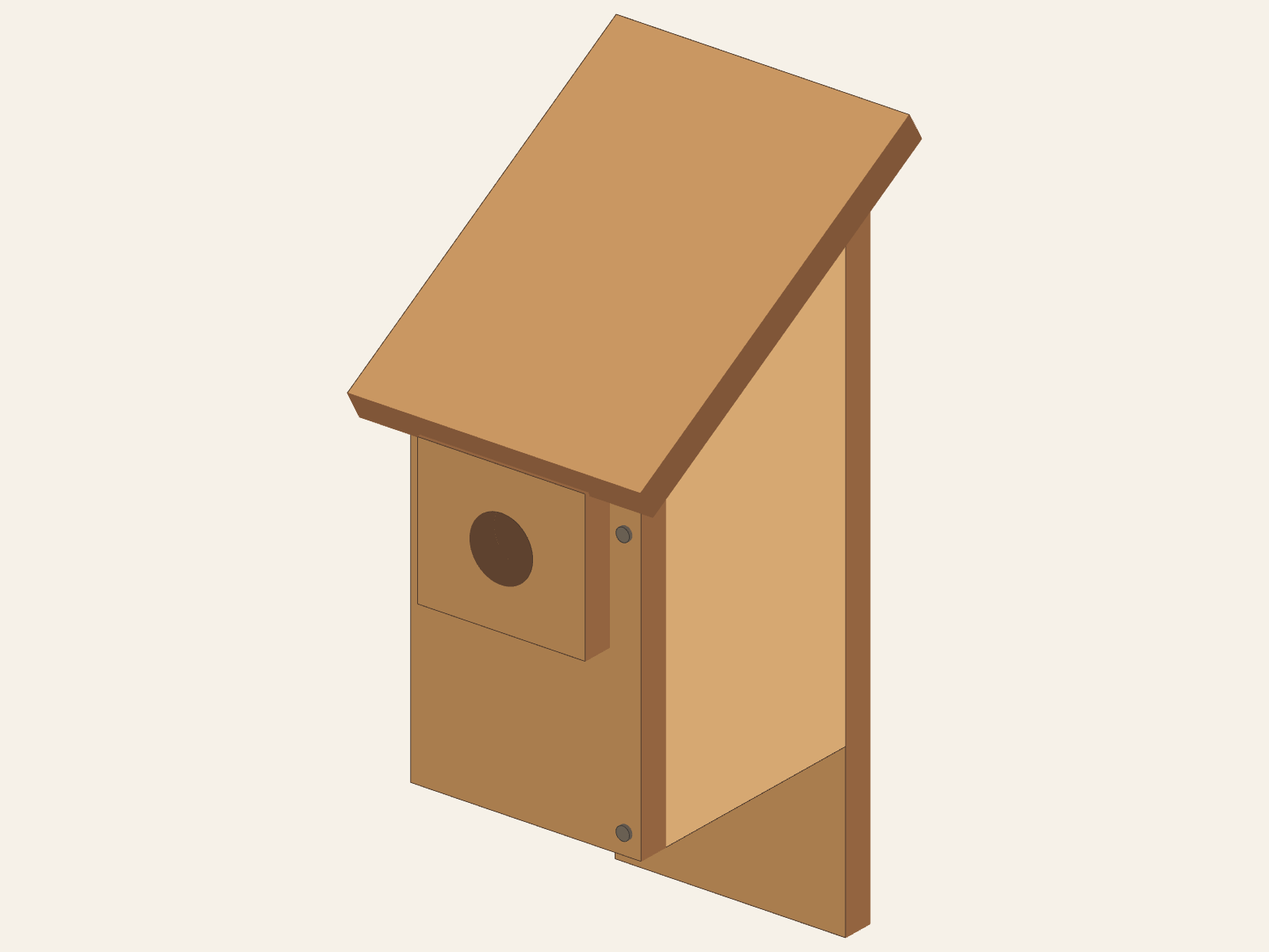
How this bird house fits together
OSU's plan uses a single roof that rises toward a long back board. A separate guard surrounds the front entrance. One side pivots for cleaning after its lower screw is removed. This lesson helps a learner identify and compare prepared parts while an adult controls cutting, holes, fastening, and any use decision.
Identify the seven wood parts
The source supplies one 1 × 6 board with an actual ¾ × 5½ in cross-section and a 54-in starting length for the body pieces. It also supplies ¾ × 10 × 8 in roof stock and a ¾ × 3½ × 4 in guard blank. These are starting materials. The drawing shows a 7-in-wide, 9½-in sloping roof and a 4-in-wide guard; it does not give a separate finished cut list for every body piece.
- Front and long back
- The front carries the 1½-in entrance. The back rises to the high roof end and extends 4 in below the body.
- Two sloping sides
- One stays fixed. The cleaning side is 1⁄16 in shorter for pivot clearance.
- Bottom
- Four ⅜-in through-drains, one near each corner.
- Guard and roof
- The guard frames the entrance without a perch; one sloped roof covers the body.
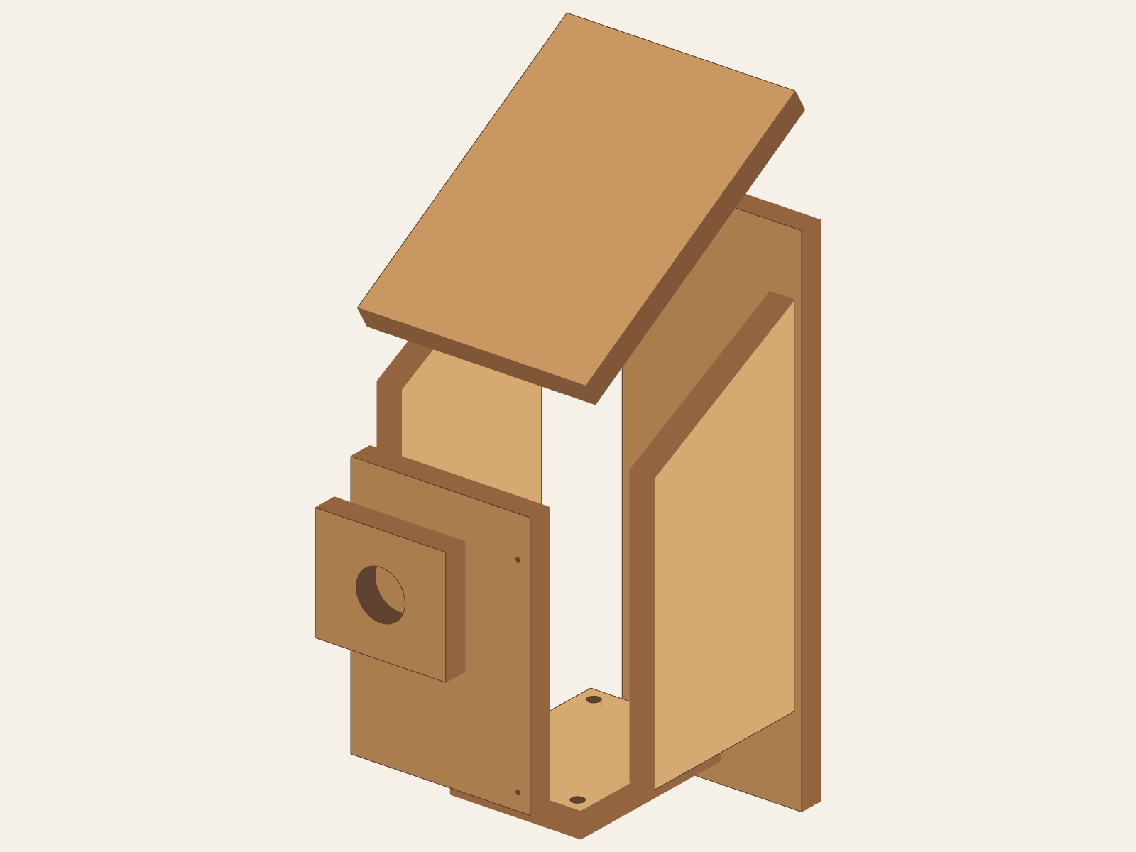
Use the original drawing with an adult to check the prepared parts. The pictured registration of the panels, drain-hole inset, and roof overhang are TWG interpretations where OSU does not give exact marks.
Prepare with an adult
Adult-controlled: select and measure actual stock; make all cuts and openings; choose pilot bits and screws; use nails, screws, boring tools, and any finish; inspect the parts and the chosen use. The Stage 2 badge describes the learning path, not tool permission.
Your check: name the front, extended back, two different sides, four-hole bottom, guard, and roof. Compare the 1½-in entrance, ⅜-in drains, pivot and removable-screw locations with the OSU drawing. Try only an unfastened, no-force dry fit when the adult has checked the prepared parts.
Follow the six source steps
Mark and cut the pictured parts
The adult reads the front, side, and finished roof views before cutting. The front is 5½ in wide and 8 in high; the back includes a 4-in extension below the body. The roof is one 7-in-wide board, 9½ in along its slope. The drawing rounds that slope to 30°. The adult verifies a complete cut layout and cutting loss against the actual starting stock.
Sand the prepared parts
OSU calls for smooth pieces. The adult checks edges and workholding before separately releasing any supported hand-sanding task. No saw, rasp, boring, or fastening task is released by this lesson.
Make four bottom drains
The adult makes a ⅜-in drain hole in each corner of the bottom. The underside view shows four real openings; the drawn inset is a model choice rather than an OSU measurement.
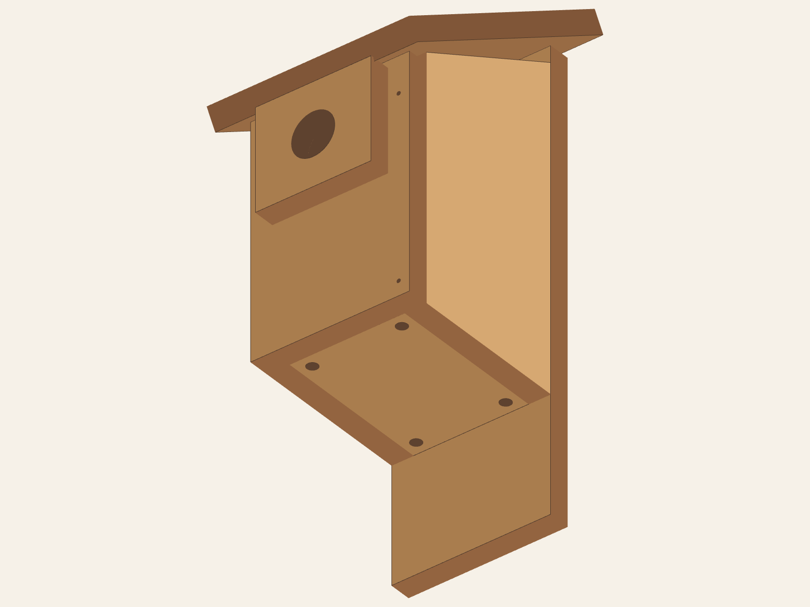
Four corner drainsThe model cuts four ⅜-in through-holes near the bottom corners. Their exact inset is an illustration choice; OSU says one drain in each corner. Prepare the cleaning-side screw holes
The adult locates the pivot screw paths in the front and back and the removable lower screw in the front. OSU refers to its printed page 17 for pilot-hole guidance; that page is PDF page 6 of the separate Woodworking Tools file linked below. The illustration shows the three screw locations, not a prescribed pilot diameter, exact screw mark, or drilling setup.
Join the fixed body, guard, and roof
The adult uses the source's 1¾–2¼-in galvanized or aluminum nails for the fixed body and 1¼-in nails for the roof and guard. OSU does not give a nail count or exact nail coordinates. First compare the body without its cover, then see the guard opening aligned with the front and the single roof above it.
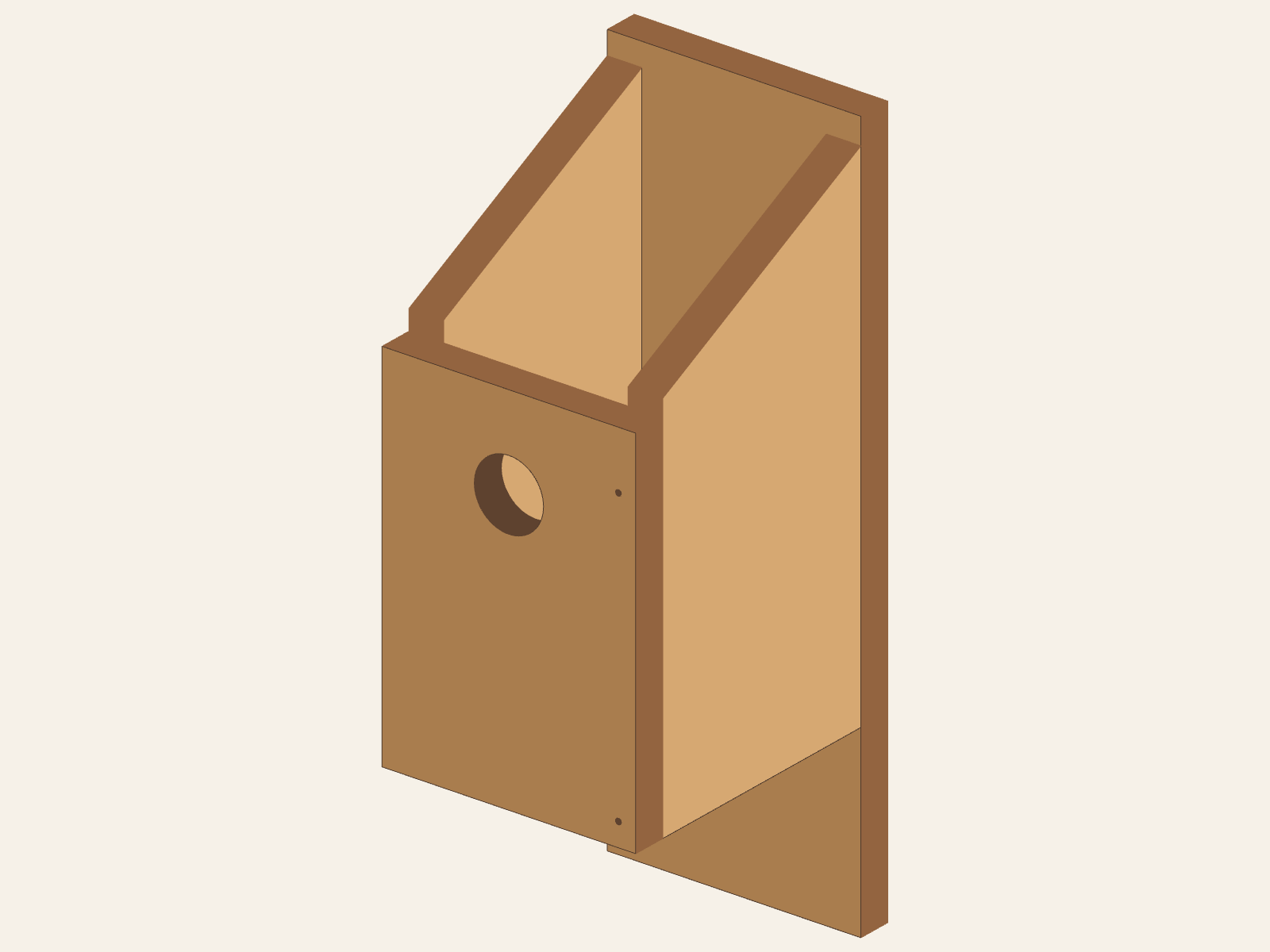
Body before guard and roofThe front, back, sides, and four-drain bottom show the body relationships before the separate guard and roof cover them. The tall back continues four inches below the body. 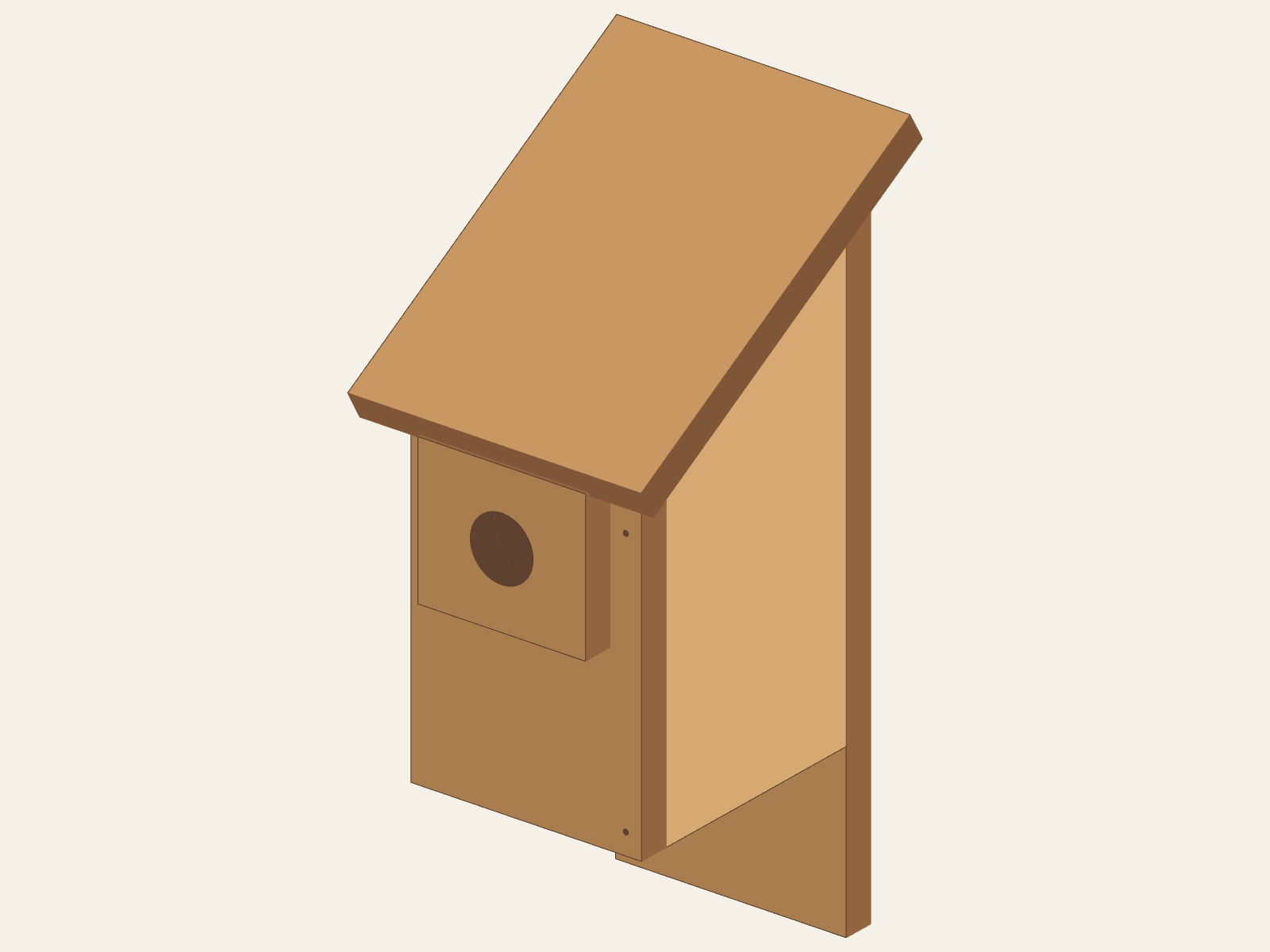
Guard and one sloped roofThe four-inch guard opening lines up with the front entrance. A single roof slopes up toward the extended back; no perch or gable roof is part of this plan. Install the cleaning side with screws
OSU lists three No. 10 × 1½-in round-head wood screws: two act as upper pivots in the front and back, and the lower front screw is removable. Its removal lets the side's top move inward for cleaning. The adult controls the screws and checks actual clearance. This selected open view omits the lower screw and shows the same side rotating about the pivot line; it does not prove a working hinge or safe service access.
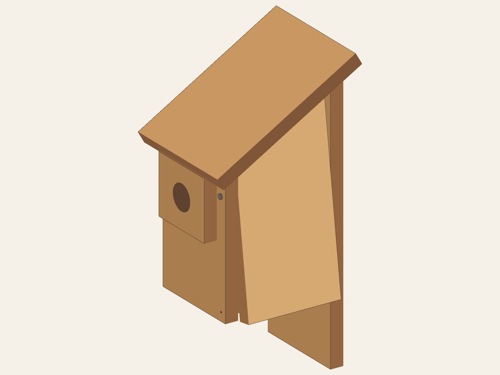
Cleaning side after lower screw removalTwo upper pivot positions remain and the lower removable screw is absent. This selected 8° display shows the top pushed inward; it does not prove physical hinge clearance or ease of cleaning.
Final inspection and intended use
An adult checks actual part contact, the roof and guard attachment, aligned entrance, four open drains, rear vent, secure pivot screws, removable lower screw, side clearance, exposed edges, and the selected material and product requirements. A learner can point to each feature and report gaps or binding without forcing the side.
The OSU construction drawing does not establish current habitat suitability, predator resistance, weather performance, mounting suitability, or a safe service life. Decide placement and wildlife use separately using current local guidance and an adult assessment.
Read both original sections
Open Bird House plan · printed p. 23Open pilot-hole guidance · printed p. 17
OSU's Woodworking Plans PDF page 5 contains the Bird House. Its Woodworking Tools PDF page 6 contains the referenced printed page 17. TWG selected the precise panel registration, roof overhang, guard height, vent profile, corner-drain inset, and illustrated 8° side position where the drawing does not provide construction marks. The model has not been physically built or approved for wildlife use.