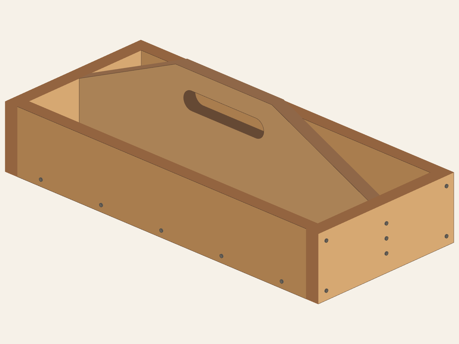
Follow the lengthwise handle
OSU's Tool Box has two long sides, two ends, a bottom, and a broad carrying panel that runs the full length between the ends. The hand opening is a horizontal slot through that panel. Use the two original pages with an adult while you compare the prepared parts and fastening directions.
Identify the six boards
The two sides start at ¾ × 3½ × 18 in. The two end blanks start at ¾ × 3½ × 10 in. The bottom is ¾ × 7¼ × 18 in, and the handle is ¾ × 5½ × 18 in. The drawing shows an approximately 8¾-in overall width, so the pictured end boards are trimmed to 8¾ in. OSU says to adjust that width for the actual bottom and side thicknesses; a 10-in blank is not a 10-in finished end.
- Two sides and two ends
- Long sides meet the bottom edges; the shorter ends close the 18-in span.
- Bottom
- The 7¼-in board fits between the ¾-in-thick sides, giving the pictured approximately 8¾-in outside width.
- Handle
- One broad lengthwise panel rises above the sides, slopes at each end, and carries a 5 × 1 in horizontal through-slot.
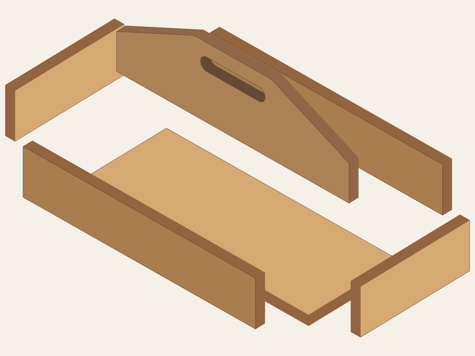
The slot centerline is 1½ in below the flat handle top. Compare that callout with the drawing; use the actual stock and source before any real layout.
Prepare with an adult
Adult-controlled: check actual stock; cut the boards and sloped handle; bore and shape the slot; choose pilot holes and countersinks; drive every structural screw; check actual fit and any use decision. The Stage 2 label describes this learning path and does not grant tool permission.
Your check: label both sides, both ends, the bottom, and the handle. Compare the horizontal slot and the end slopes with printed p. 29. An adult may separately approve supported hand-sanding of a prepared edge or a no-force dry fit after checking the parts.
Follow the seven source steps
Cut the parts to size
The adult compares the material list on printed p. 28 with the drawing on p. 29. The model trims the 10-in end blanks to a selected 8¾-in finished width, accounting for a 7¼-in bottom plus two ¾-in side thicknesses. Check actual stock before marking those end cuts.
Mark and cut the handle slopes
The handle runs 18 in lengthwise. The drawing divides its top into two 6-in slopes and a 6-in flat center; the center rises 2¾ in above the 3½-in side height. The adult leaves material for sanding as OSU instructs.
Make and smooth the hand opening
The source places the centerline of its 5 × 1 in horizontal opening 1½ in below the flat handle top. The adult controls the 1-in boring tool at each end, the connecting saw cut, rasp or file, and final edge check. The model shows an actual through-slot, not a drawn mark.
Connect handle and bottom
OSU marks a lengthwise centerline on the bottom and five pilot/countersunk holes at 3-in spacing. The adult uses five No. 8 × 2-in screws from the underside into the centered carrying panel. Compare the five central heads with the underside view.
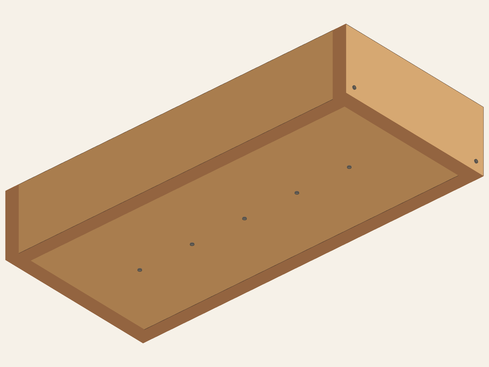
Bottom fastening viewFive 2-in screws run from the bottom into the lengthwise handle at 3-in spacing. Four 1½-in screws run from the lower end corners into the sides. Add both sides
OSU places the side screw line ⅜ in from the bottom edge and shows five locations per side. The adult pilots and countersinks, then drives No. 8 × 2-in screws through the sides into the bottom. Compare the five-board case before the handle covers its center.
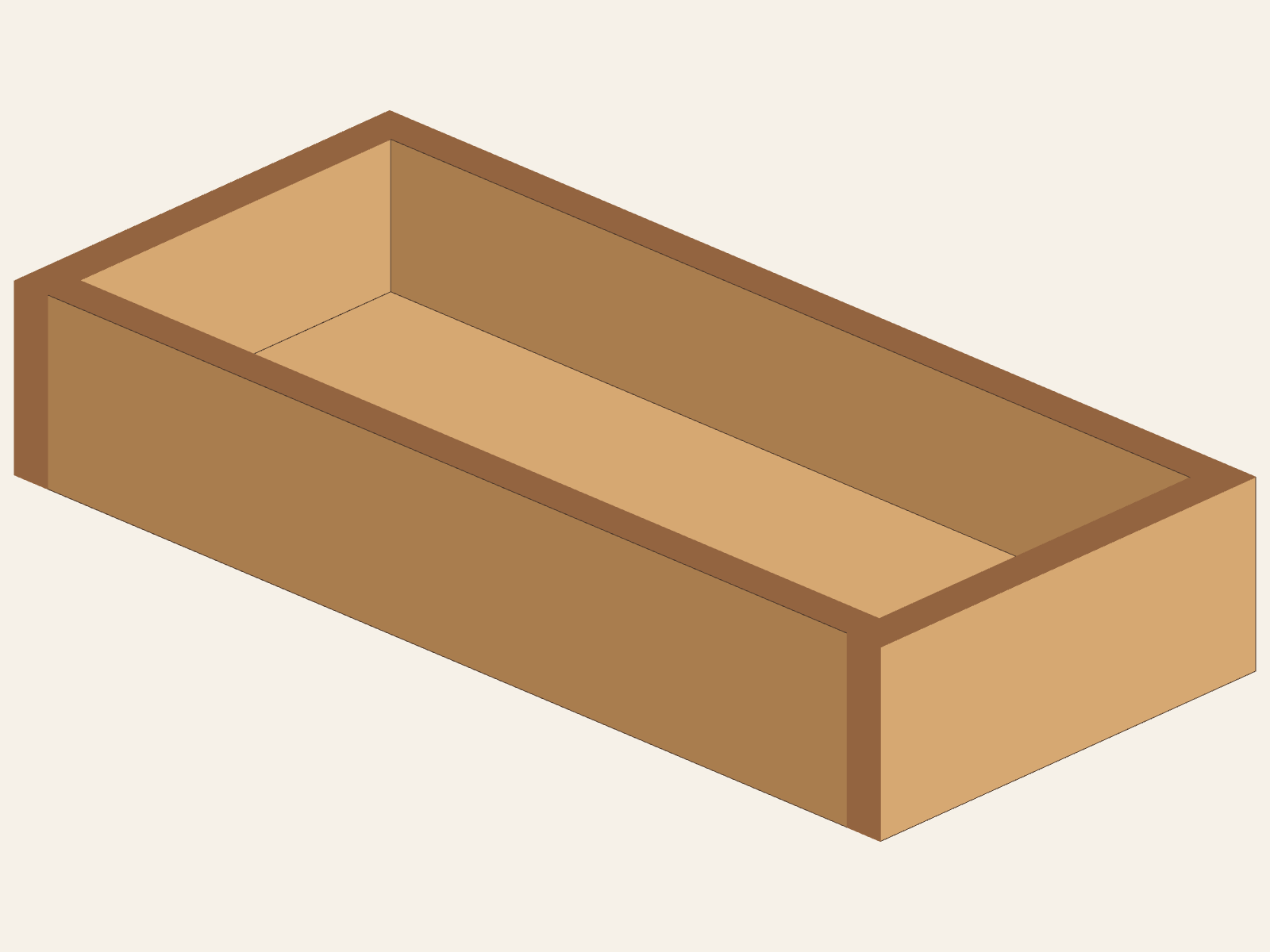
Bottom, sides, and endsThe bottom meets both long sides; each end closes the board edges. The handle panel is omitted in this stage to reveal those contacts. Add the ends
The ends close the exposed side and bottom edges. The adult uses No. 8 × 2-in screws at the upper end-to-side corners, and the four listed No. 8 × 1½-in screws at the lower end-to-side corners. Both corner rows enter the outer side strips; the narrower bottom board lies between them. The screw centers are ½ in from the nearest end-board edges.
Secure the handle at both ends
OSU calls for three pilot/countersunk holes in each end for the handle and a No. 8 × 2-in screw in each. The illustration also shows the side and low corner screw groups. The model checks that each pictured screw path ends inside its intended receiving board; real hole marks, countersink depth, and screw seating require adult checks on actual stock.
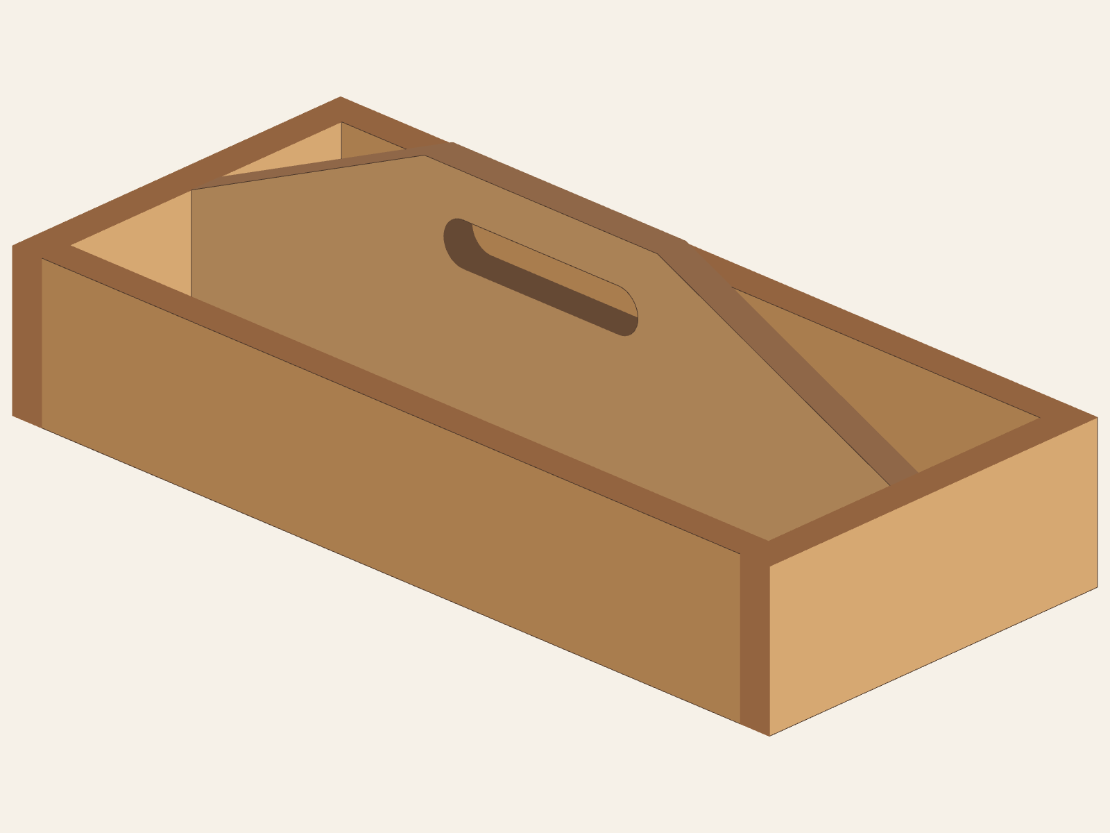
Lengthwise handle relationshipThe broad handle rests on the bottom between the ends. Its top rises at both ends to a flat center and its horizontal hand slot goes through the panel. 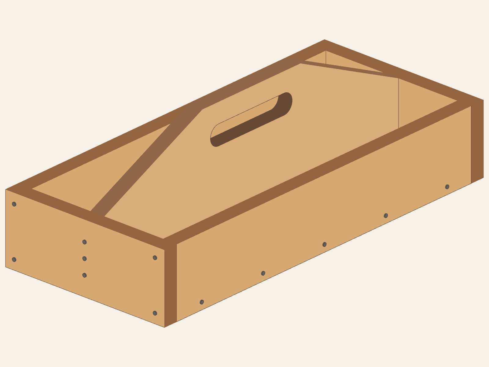
End and side fastening viewThree 2-in screws from each end meet the handle; upper end screws meet the sides; the low end screws meet the sides. The side screw line also meets the bottom.
Final inspection and intended use
An adult checks the actual side, bottom, end, and handle contacts; the open and smooth hand slot; exposed edges; pilot/countersink results; seated screw heads; and any intended contents or carrying use. A learner can identify the five screw paths and report a gap, loose piece, or protruding tip without testing a load.
The drawing and this model do not establish safe carrying weight, handle strength, fastener adequacy, or physical fit. No loaded-use permission follows from the Stage 2 label or a matching image.
Read the instructions, drawing, and pilot-hole section
Open instructions · printed p. 28Open drawing · printed p. 29Open pilot-hole guidance · printed p. 17
The plan pages are PDF pages 10–11 of OSU Woodworking Plans. The pilot-hole reference is PDF page 6 of the separate OSU Woodworking Tools file. OSU dimensions the slot centerline 1½ in below the flat top and outer end heads ½ in from adjacent edges. TWG selected only the remaining undimensioned screw centers for illustration. The end width shown here is a fit interpretation permitted by the source's adjustment note. No physical build or load test has been performed.