
Winding Sticks
Make twist easier to see by comparing two straight references across a board, then separate that reading from cup, bow and overall flatness.
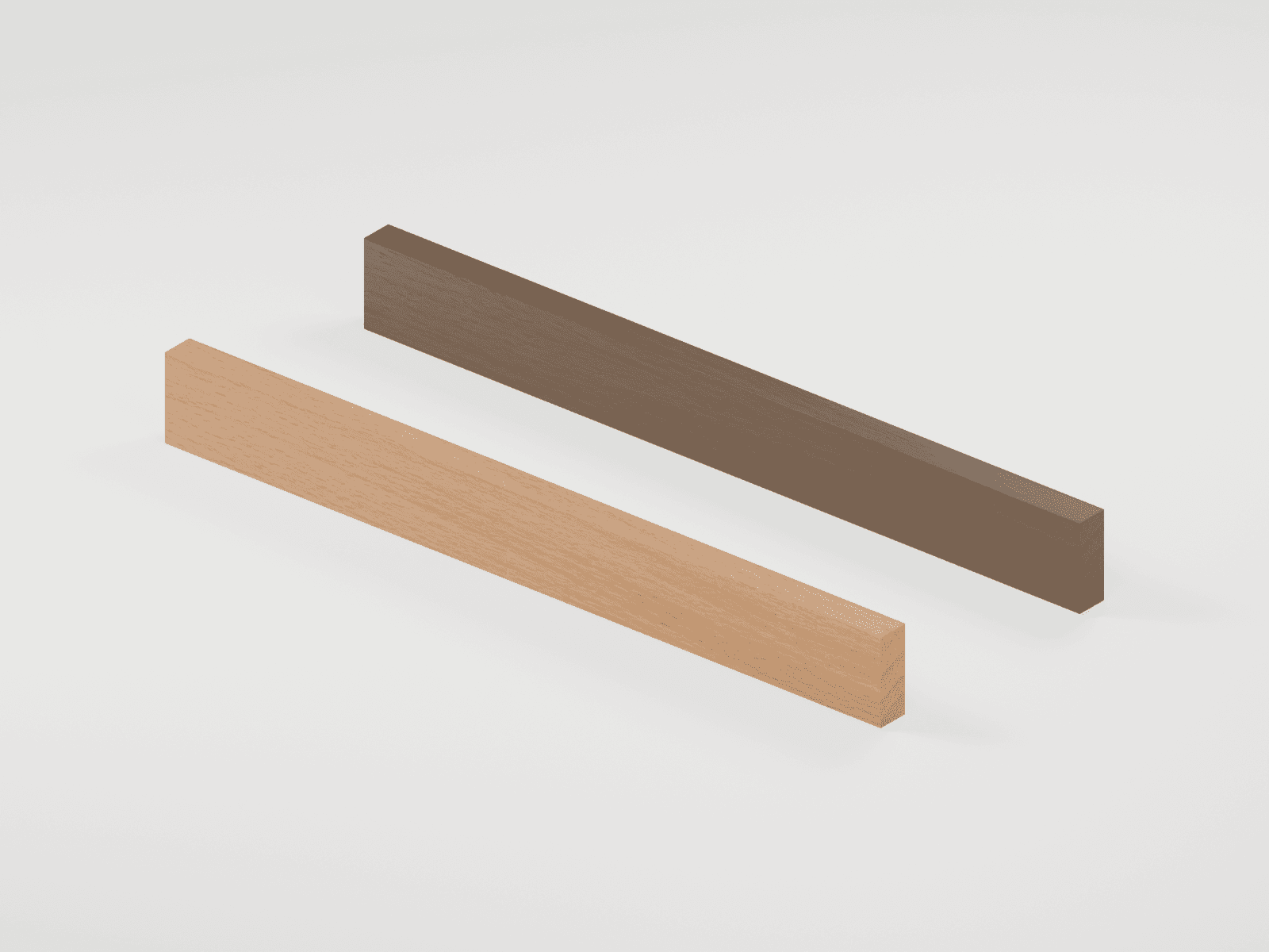
See the intact tool and its features
An original educational poster identifies 4 documented features of this tool. The numbered descriptions remain readable below the artwork on narrow screens.
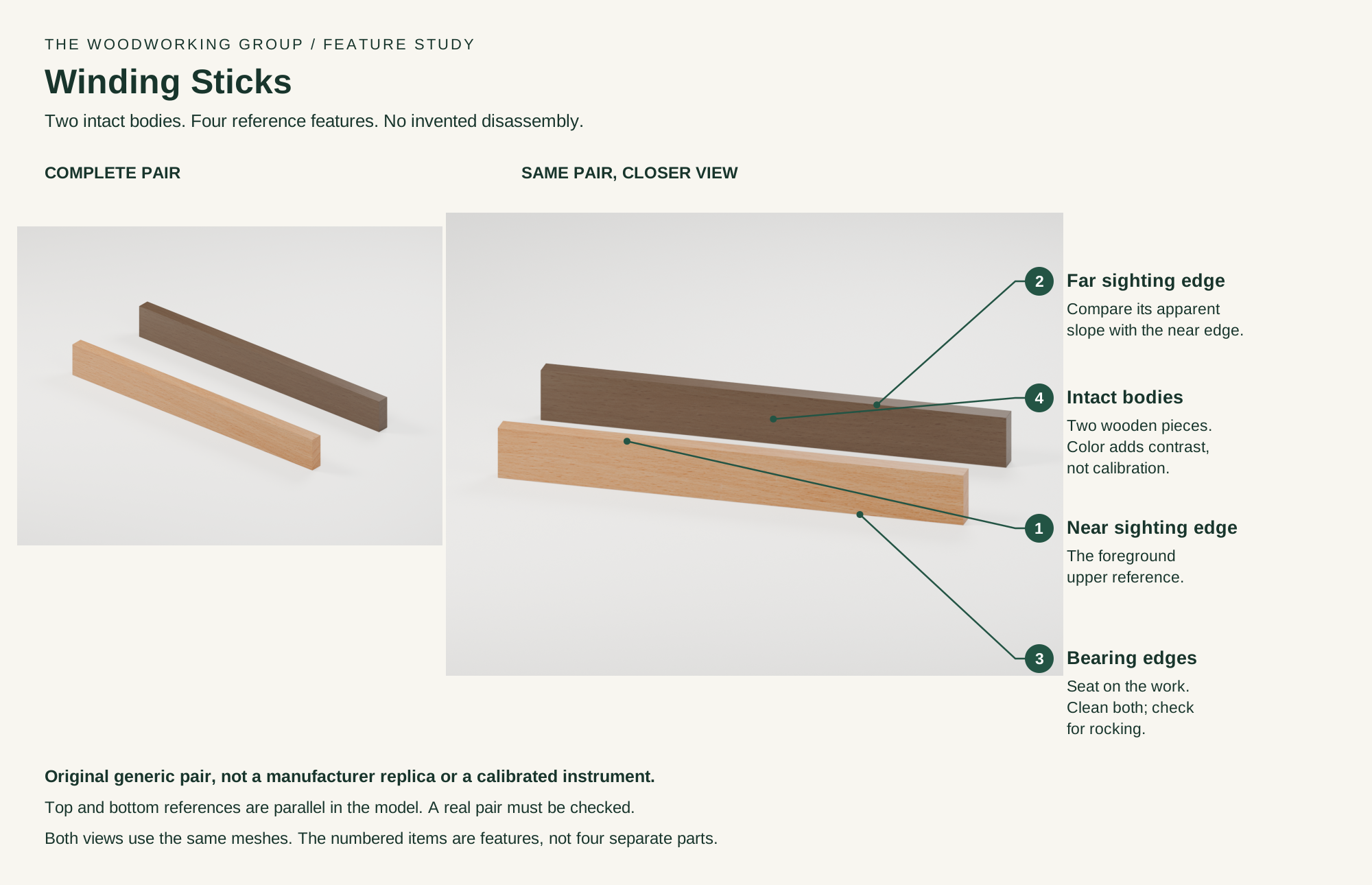
- Near sighting edge
Foreground upper reference for comparing the far top edge.
- Far sighting edge
Background upper reference whose apparent slope is compared with the near one.
- Bearing edges
Bottom references seat on the work. Both must be clean and stable.
- Intact bodies
Carry the straight references. Different colors improve contrast, not accuracy.
Technical references: Red Rose winding-stick design and use · Precision instruments · What are winding sticks?. The same two original meshes appear in both studio views; only the camera changes. Each modeled body is 18 by 3/4 by 2 inches with straight parallel reference edges. Those dimensions are illustration choices, not a manufacturing tolerance or calibration claim. No board, inlays, sight windows or adjustment mechanism is shown. Original educational artwork depicts the intact tool and magnified features; the additional views are not detachable parts.
What it is and what each part does
Winding sticks extend two crosswise references beyond the edges of a board so a small difference in their slopes is easier to see. A straightedge checks gaps along a line; winding sticks compare two transverse positions. A spirit level references gravity. A board need not be level to be free of twist.
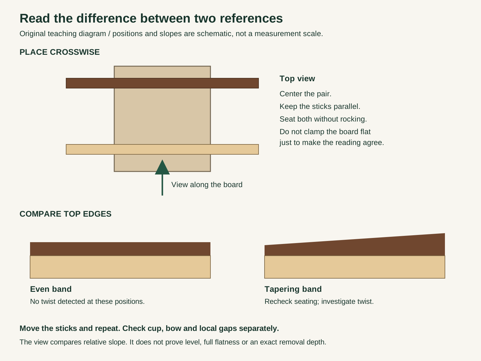
Seat one stick across each of two positions, centered on the stock and square to its length. Sight along the board, lowering your eye until a narrow band of the far stick is visible above the near one. Nonparallel top edges indicate a difference in the supporting crosswise slopes, provided the sticks are sound and properly seated. An even band means no twist was detected between those positions; it does not certify the entire surface flat.
1. Near sighting edge
The upper edge of the nearer stick provides the foreground reference. Keep it clean, straight and clearly visible.
2. Far sighting edge
Compare the far upper edge with the near one. A contrasting face or background makes a tapering band easier to distinguish.
3. Bearing edges
The bottom edges contact the work. A chip, dent, crown or rocking contact can give a misleading reading.
4. Intact bodies
The two bodies carry those references. Their modeled top and bottom edges are parallel; color does not substitute for accuracy.
How the main groups connect
Set, guide and control the action
These decisions make the mechanism useful at the bench.
Start with trustworthy sticks
Inspect both pairs of reference edges. Warped or tapered sticks can imitate twist. This model is not a calibration certificate.
Align the pair
Place the sticks crosswise, approximately perpendicular to the board length, parallel to one another and centered. Skewed placement can confuse the comparison.
Seat without distortion
Support the stock securely without clamping it artificially flat. Check that neither stick rocks on chips, a ridge or a convex patch.
Assess rough stock
Compare several positions before deciding how to prepare the board. Do not assume the first reading identifies all high areas.
Check between hand-planing passes
Move cutting tools aside, clear shavings and repeat the same sighting setup. Mark verified high regions before removing more wood.
Check an assembly for twist
Use suitable contact surfaces across a frame or benchtop, while accounting for its support and restraint. Diagonal length checks answer a different question.
Setup, technique and finish quality
Use the steps for a first pass, then inspect the work before changing the setup.
- Inspect the sticks and clean the work and bearing edges. Arrange stable support without forcing the stock into a different shape.
- Set one stick near each end, crosswise and centered, with both standing securely on their intended bearing edges.
- Choose a clear, contrasting background. Stand back along the board length and lower your eye toward the near top edge.
- Compare the amount of far edge visible at the left and right ends. A tapering band is a signal to investigate relative twist.
- Re-seat and realign the sticks if the reading is uncertain. Do not remove material based on a rocking or poorly lit setup.
- Move one stick to intermediate positions and repeat. Use a straightedge separately for cup, bow and local hollows.
- Remove the sticks before cutting. After any correction, clear debris and check again from the same reference setup.
Twist is not the same as level
A flat board may slope relative to the floor while its two transverse references remain parallel. A bubble reading is not this test.
A clear sight picture is conditional
A parallel pair of top edges compares the locations under the sticks. Untested regions can still be bowed, cupped, hollow or otherwise uneven.
Long references reveal small differences
The overhanging ends make small angular differences easier to see. This ungraduated pair is not a direct measurement of how much wood to remove.
Two pieces, four named features
The numbered poster describes two sighting edges, bearing edges and bodies. These are features of the intact pair, not four removable components.
What changes by model or material
Shop-made sticks can use contrasting wood, paint or inlay for visibility. Decoration must not damage or obstruct the reference edges.
Some makers use openings and a narrow bridge to create a light reference. Those cutouts are not part of the plain pair illustrated here.
Purpose-made aluminum pairs can have contrasting faces and nested storage. A random extrusion is not automatically straight, undamaged or suitable.
Choosing the tool
- Choose enough length to overhang the work while remaining manageable.
- Check stable seating and straight, mutually appropriate reference edges.
- Favor a readable contrast under the lighting where you actually work.
Useful accessories
- Straightedge for separate flatness checks
- Pencil or chalk for recording checked regions
- Stable supports and appropriate workholding
- Protective storage for the reference edges
Care, troubleshooting and safety
Secure the work, protect sharp edges and release any stored clamping pressure before adjustment or maintenance.
Care checklist
- Brush off dust and dried residue before each reading.
- Protect the edges from drops, dents and pressure in storage.
- Check wooden sticks after moisture or storage changes; re-true or replace a suspect pair.
Common mistakes
- Calling a parallel sight picture proof of complete surface flatness.
- Setting the pair diagonally or leaving chips under one end.
- Reading a board while clamps are forcing it flat.
- Using a marked or damaged edge without checking it.
Safety at the operation
- Stabilize large or heavy stock before crouching to sight along it.
- Move sticks, measuring tools and loose supports clear before machining or planing.
- Keep hands clear of cutting edges while checking a surface.
- Any machine-table alignment is a separate, powered-off procedure governed by that machine manual. These sticks are not a guard, clamp or adjustment instruction.
When the result goes wrong
Clear debris, check rocking and stock support, then restore the same stick positions and viewing direction.
Change the background, lighting or contrast arrangement. Lower your eye gradually rather than guessing from above.
Check more positions and use a straightedge for bow, cup and local gaps. The pair does not test every part of a surface at once.
Inspect and re-seat both sticks. Changing their positions can expose inconsistencies, but does not by itself certify their accuracy.
Manuals and educational resources
Use the exact model documentation for setup, limits and replacement parts. These lessons, documents and model pages teach relevant techniques or help compare real variations.
Manufacturer documentation
Learn and compare
Precision instruments
Dan Schwank explains stable stock and reference preparation for his winding-stick design.
What are winding sticks?
Highland Woodworking describes crosswise placement, contrast and misleading contact on a crowned surface.
How to make and use winding sticks
Charles Mak discusses contrast, different stick lengths and the distinction between the illustrated designs.
General hand-tool operation
CCOHS guidance for inspection, clear work areas and safe handling around cutting tools.
Manufacturers & Brands
These maker-owned links document relevant tools and tool brands. A product brand may use another company's factory; compare the exact model before choosing parts or accessories.
Choose parts for the exact model
Handles, irons, saw plates, clamping pads and other replacements vary by maker and model. Use the maker's documentation before changing a component.
Compare the Layout Tools family →Continue through the Tools library