
Head valve, cylinder and driver
The official parts list separates top cover, valve spring and head valve, piston with attached narrow driver, cylinder plate and bumper.
Drive small U-shaped staples for trim, cabinetry and light assembly with controlled pneumatic fastening.
An original educational poster identifies 11 documented construction features. The numbered descriptions remain readable below the artwork on narrow screens.
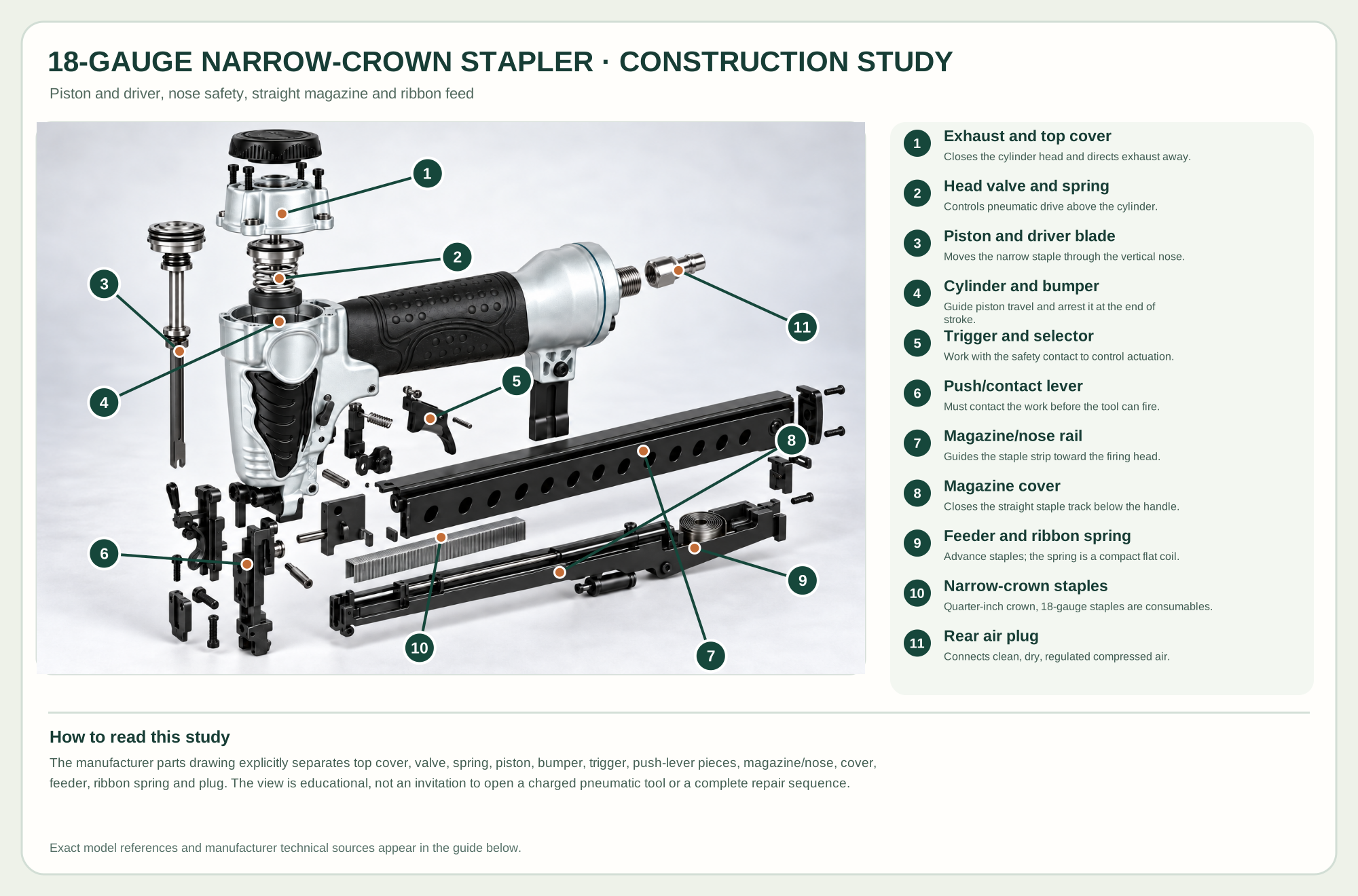
Closes the cylinder head and directs exhaust away.
Controls pneumatic drive above the cylinder.
Moves the narrow staple through the vertical nose.
Guide piston travel and arrest it at the end of stroke.
Work with the safety contact to control actuation.
Must contact the work before the tool can fire.
Guides the staple strip toward the firing head.
Closes the straight staple track below the handle.
Advance staples; the spring is a compact flat coil.
Quarter-inch crown, 18-gauge staples are consumables.
Connects clean, dry, regulated compressed air.
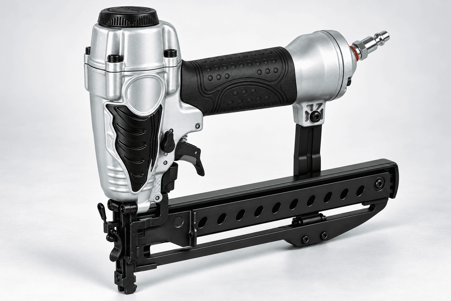
Technical references: Metabo HPT N3804AB3 official product · Metabo HPT N3804AB3 official parts list E037 · Metabo HPT N3804AB3 official owner manual. The manufacturer's E037 parts list locates the piston and attached narrow driver above the vertical firing nose. A push/contact lever and trigger control firing. The straight under-handle magazine holds 18-gauge, quarter-inch crown staples; its feeder is returned by a compact ribbon spring, not a long helical spring. Original educational artwork depicts documented component groups and their relationships; it is not a service sequence or a replacement for the exact model manual.
Metabo HPT's N3804AB3 drives 18-gauge, 1/4-inch narrow-crown staples from 1/2 to 1-1/2 inches long at a recommended 70–120 psi. The straight magazine holds up to 100 staples. It is not an 18-gauge brad nailer: each U-shaped staple has two legs and a connecting crown. The brand-neutral TWG render follows the official assembled photo and manufacturer E037 parts breakdown, preserving the head-to-handle and under-handle magazine relationship without reproducing logos.
Clean, dry, regulated air enters the rear handle fitting. A trigger and moving contact/push lever enable the pneumatic head valve. The piston and its attached narrow driver blade travel down the vertical cylinder and firing nose to drive one U-shaped staple. A straight magazine/nose rail, spring-fed staple feeder and compact flat ribbon spring advance the next fastener. The construction view shows documented groups separated along their real axes; opening a charged tool is not an operating step.
The official parts list separates top cover, valve spring and head valve, piston with attached narrow driver, cylinder plate and bumper.
The user trigger works with the contact safety at the nose. The actuation selector offers sequential or contact operation under the manual's specific rules.
The straight under-handle rail holds a quarter-inch crown staple strip. A compact ribbon spring feeds it; there is no long exposed coil along the magazine.
The tool-free depth adjuster, guide plate and no-mar nose cap affect where the staple exits and how it sits in the surface.
A 1/4-inch NPT male fitting joins the regulated hose; it has no exposed coil spring behind it.
These decisions make the mechanism useful at the bench.
Use a regulated compressor within the 70–120 psi range. Never supply oxygen, fuel gas or unregulated pressure.
Disconnect air before loading, checking the nose or clearing jams. Follow the maker's sequence for selective actuation.
On matching scrap, keep the nose square, test the contact lever and adjust air pressure or depth only as the manual directs.
Hold thin panels on supported frames with suitable staple length and spacing, while ensuring the points cannot pass through.
Use small crowns where their visibility and holding pattern are appropriate, often alongside adhesive or sound joinery.
Fasten thin jigs or covers only when the underlying material and staple penetration are controlled.
Use the steps for a first pass, then inspect the work before changing the setup.
The narrow crown bridges two legs, leaving a different surface mark and holding pattern from a single small nail.
Contact actuation can double-fire after recoil if the nose recontacts the work. Use the manual's sequential setting when precise placement is needed.
A hose coupler should release pressure when disconnected; the tool can otherwise remain capable of driving a fastener.
One deliberate nose-and-trigger cycle positions a staple for accurate trim work.
The selector permits repeated contact firing only with the controls and recoil discipline described by the maker.
The supplied cap reduces surface marking; inspect it for wear and verify full safety-lever travel.
Stop the tool and disconnect power before investigating a fault or changing a part.
Check pressure in range, depth adjustment, staple length and whether the nose is square to supported material.
Disconnect air, inspect correct staple size, feeder/ribbon spring motion and the guide plate; follow the manual's jam procedure.
Stop, verify sequential/contact selector position, recoil control and contact-lever action before reuse.
Use the exact tool manual for setup, limits and replacement parts. These lessons, documents and model pages teach relevant techniques or help compare real variations.
Official operating pressure, fasteners, firing controls, loading, maintenance and safety instructions.
Official exploded drawing and individual head, piston, nose, magazine, feeder and ribbon-spring parts.
These maker-owned links document relevant tools and tool brands. A product brand may use another company's factory; compare the exact model before choosing parts or accessories.
Cutters, abrasives, guards, guides, dust fittings and service parts vary by tool. Check the model plate and manufacturer manual before ordering or changing a component.
Compare the Joinery family →Continue through the Tools library