
Bench Hook
Understand the three-board stop that steadies a small hand-sawing job, and why its holding direction matters.
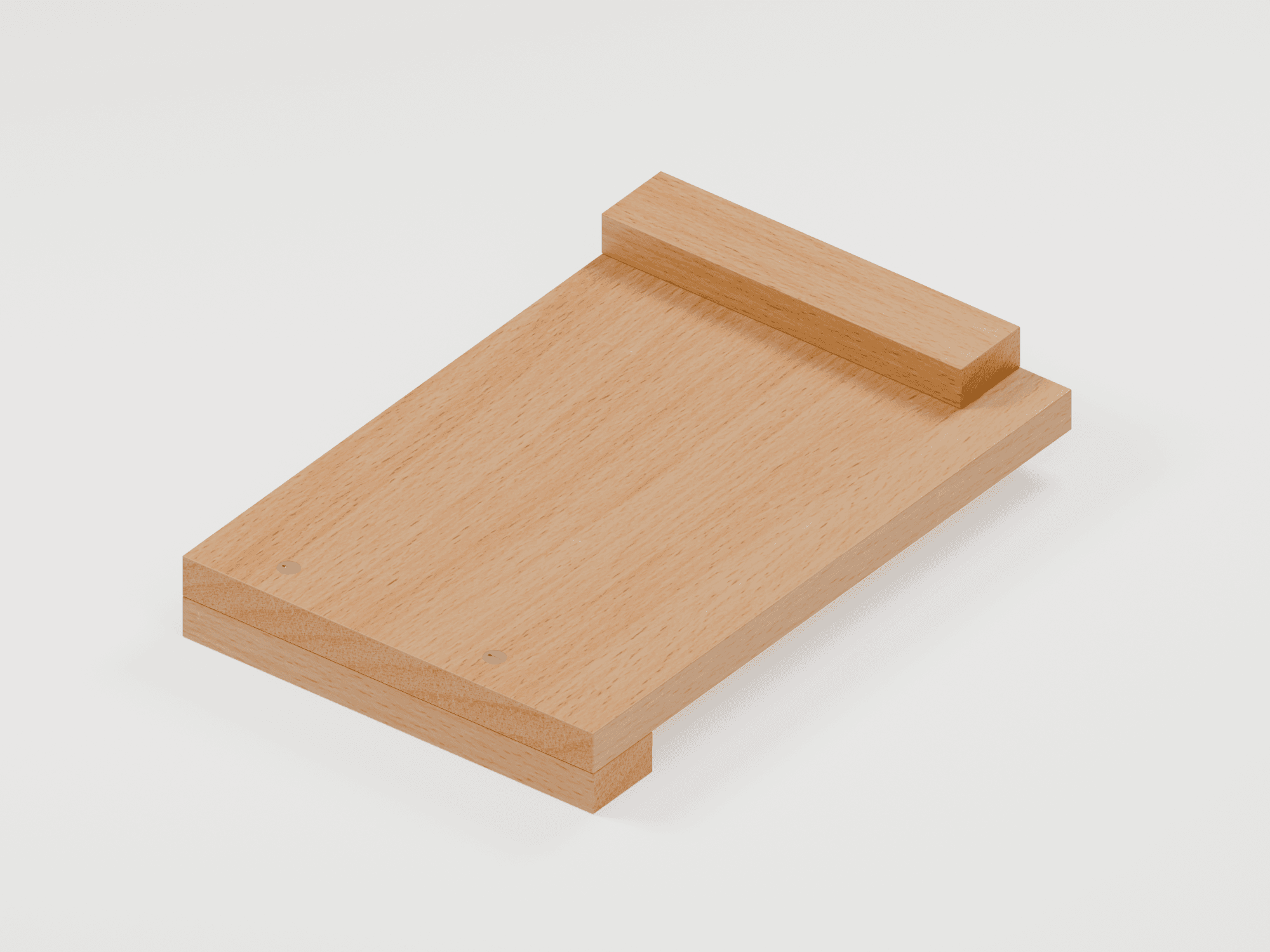
See the assembled tool and its components
An original educational poster identifies 5 documented construction features. The numbered descriptions remain readable below the artwork on narrow screens.
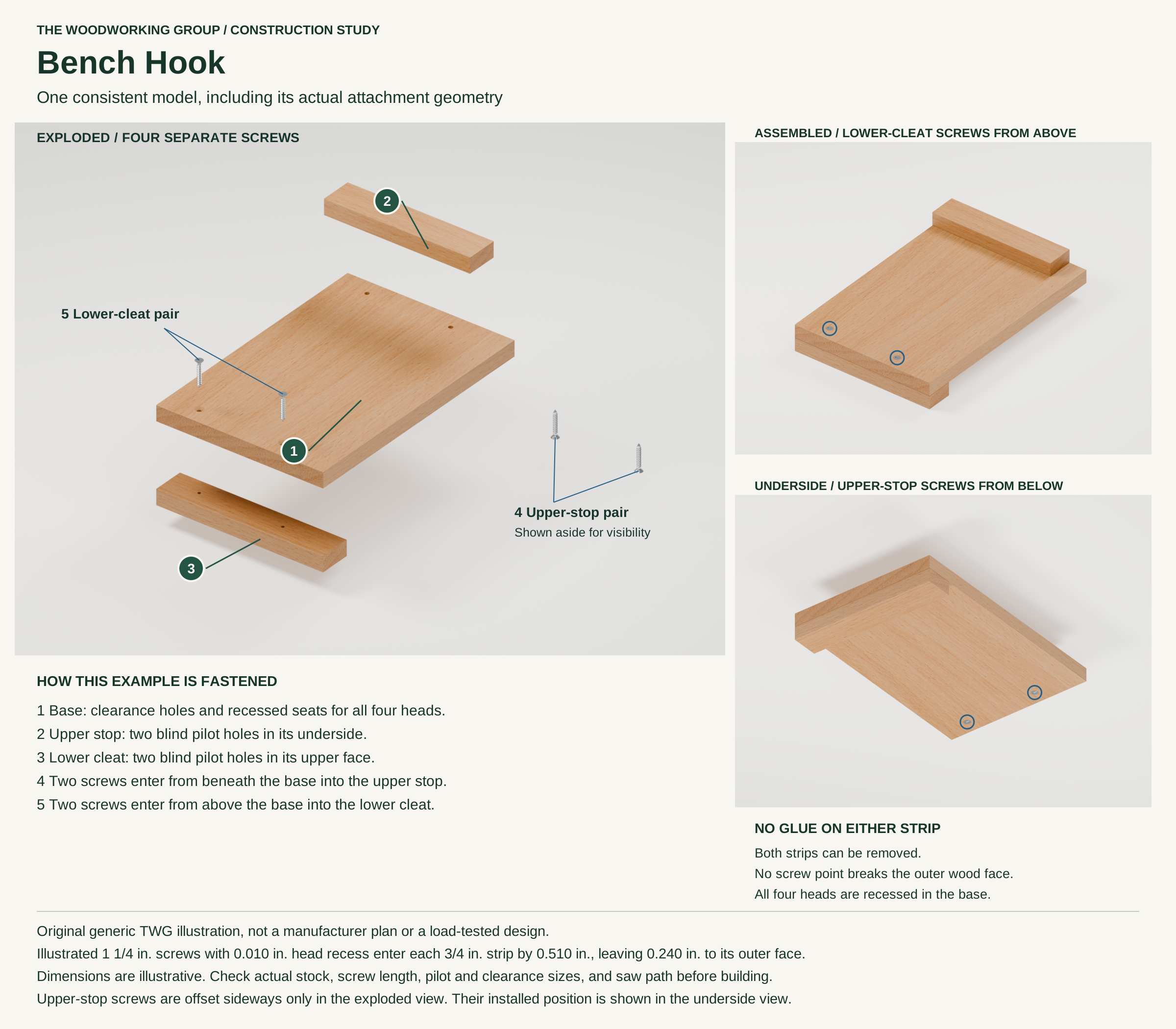
- Base
Supports the work. Its four clearance holes and countersinks receive the two screw pairs. Deep cuts can still reach the bench.
- Upper stop
Registers the work and leaves one inch of right-side saw clearance. Two blind pilot bores receive screws from below.
- Lower cleat
Meets the front bench edge to oppose forward push. Two blind pilot bores receive screws from above.
- Upper-stop screw pair
Two recessed screws pass upward through the base into the upper stop. This pair is shown sideways-offset only in the separated view for visibility.
- Lower-cleat screw pair
Two recessed screws pass downward through the base into the lower cleat. Neither head projects above the work-support surface.
Technical references: Making a Bench Hook · Bench hooks and bench dogs · Bench stops and hooks. One original model supplies all three views: a 12 by 8 by ¾-inch base, 7-inch upper stop, 8-inch lower cleat and four 1¼-inch screws. All boards are ¾ inch thick. Two screws enter upward through the base into the stop, and two downward into the cleat. No glue joins the strips. This is an illustrative construction choice, not a tested build plan. This original construction is for teaching, not a tested build plan, manufacturer replica or service sequence.
What it is and what each part does
A bench hook gives a small workpiece a stop and a sacrificial support surface. Unlike a vise, it does not close around the work. Unlike a miter box, this plain version has no slot to control the saw angle. The user still guides the cut and keeps the work seated.
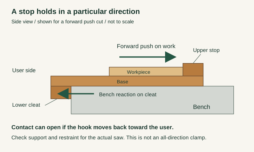
In the illustrated push-cut arrangement, the lower cleat bears against the front edge of the bench. Forward force on the work passes into the upper stop and then through the base to that cleat. The bench opposes the hook's movement away from the user. This contact does not prevent lifting, sideways slipping or movement back toward the user.
1. Base
The broad board carries the work. Its top is a sacrificial surface, not a guarantee that a deep cut cannot reach the bench.
2. Upper stop
The work bears against its front face. The shorter stop leaves clearance on the right side in this original right-handed teaching model.
3. Lower cleat
The cleat is underneath the opposite end. Its inner face meets the bench edge to oppose a push away from the user.
4–5. Two screw pairs
In this original example, two screws go upward through the base into the upper stop; two go downward through the base into the lower cleat. Both strips are removable, with no glue between them and the base.
How the main groups connect
Set, guide and control the action
These decisions make the mechanism useful at the bench.
Seat both contacts
Place the lower cleat fully against a suitable bench edge, then seat the work against the upper stop. Check that neither rocks.
Reserve a clear saw path
Position the cut beside the short stop, away from hands and any fastening hardware. Check where the blade will go as it exits.
Change the holding method when needed
If the work or hook shifts during a gentle dry rehearsal, stop and use a suitable vise, clamp or different jig.
Know what holds it together
This illustration uses four 1¼-inch flat-head screws with their tops recessed 0.010 inch below the base surface. Each tip reaches 0.510 inch into a ¾-inch strip, leaving 0.240 inch to its outer face. These are model dimensions, not a universal hardware specification.
Small hand crosscuts
Support a manageable piece against the stop while following a marked cut with an appropriate hand saw.
Repeated short parts
Recheck each part's seating and layout. This simple stop is not a length-setting gauge.
Bench protection
A replaceable support takes shallow saw wear. Inspect the remaining thickness and keep the actual bench outside the cutting path.
Setup, technique and finish quality
Use the steps for a first pass, then inspect the work before changing the setup.
- Inspect the base, stop and cleat for splits, looseness and damaging wear. Choose a sound, stable bench edge.
- Identify the saw's cutting direction. The model shown is arranged for a forward push cut.
- Seat the lower cleat against the front edge and support the work against the upper stop without rocking.
- Mark the waste side. Plan the whole blade path, including the exit, with fingers outside it and long stock separately supported.
- Rehearse the holding arrangement without cutting. Add suitable restraint or change the setup if anything shifts.
- Start gently, follow the layout, and reduce force near the end. Stop before reaching the bench or hidden hardware.
A stop is directional
A front-edge cleat can resist a forward push only while it remains in contact. A reverse pull can open that contact.
Registration is not guidance
A square stop helps position stock; it does not force a freely moving saw to follow a square line.
One construction in every view
The assembled, separated and underside views use the same three boards and four screw meshes. The upper-stop screw pair is offset sideways in the separated view so its orientation and heads remain visible.
What changes by model or material
A mirrored stop arrangement can put the open sawing area on the other side. Confirm the hand and blade positions together.
A pull saw changes the holding problem. Published alternatives use different stop positions or register against another bench edge; do not assume this front-edge push arrangement will restrain a pull.
Some hooks also support planing with a carefully prepared reference edge and stop. That is a separate setup, not a capability established by these studio views.
Published hooks use different bases and fastening directions. This original TWG example uses screws through the base into the strips, rather than copying one published plan. Match hardware, pilots and seating to real stock before building.
Choosing the tool
- Match size and stop position to the work and saw direction.
- Check flatness, sound joints and a usable bench-edge contact.
- Keep any screws outside the planned cutting area.
Useful accessories
- Suitable crosscut hand saw
- Layout square and marking tool
- Separate support for long stock
- Suitable additional restraint when needed
Care, troubleshooting and safety
Remove the work and saw before inspecting the base, fasteners and bench contacts.
Care checklist
- Brush chips away from the stop and bench contacts.
- Check for loosened joints, protruding hardware, splits and deep kerfs.
- Replace worn or damaged parts before reuse; do not rely on cracked wood.
- Check the four recessed heads and both strips before use. Any looseness, exposed point or proud head needs correction before the hook returns to work.
Common mistakes
- Treating the hook as a clamp in every direction.
- Assuming the stop makes the cut square automatically.
- Cutting through the sacrificial base into the bench.
- Placing a hand in the blade's possible exit path.
Safety at the operation
- Wear suitable eye protection and select a sound hand saw appropriate to the work.
- Inspect stock for metal and other defects before cutting.
- Secure the work and support long stock. Stop if the work, hook or bench moves.
- Keep fingers out of the entire blade path. This model is not a powered-saw fixture or a load-rated clamp.
- The drawn holes and screws explain one attachment choice. Real screw diameter, pilot size, countersink, stock condition and holding strength must be checked before assembly or use.
When the result goes wrong
Check cutting direction, bench-edge engagement and support. Change the restraint rather than pressing harder.
Clear chips, inspect the work and contact faces, and check the stop's attachment.
Recheck layout, saw condition and technique. A plain bench hook does not constrain the blade.
Manuals and educational resources
These independent lessons explain workholding principles and alternative construction choices. The pictured hook is an original TWG teaching model, not one of these published plans.
Learn and compare
Making a Bench Hook
Michael T Collins explains a three-piece hook, shorter stop and removable screw fastening. His screws pass through the strips into the base; the reverse direction pictured here is an original TWG choice.
Bench hooks and bench dogs
Carol Russell explains the two stops and discusses a different arrangement for Japanese saws.
Bench stops and hooks
Woodcraft's published workholding variants show why registration changes with push- and pull-cut tasks.
Hand-saw safety
CCOHS guidance on saw selection, inspection, eye protection and supported work.
Continue through the Tools library