
Dividers and Compass
Transfer a distance, repeat a spacing or draw an arc without losing the setting. Choose two steel points for transfer work and a pencil compass when the line should be drawn rather than scratched.
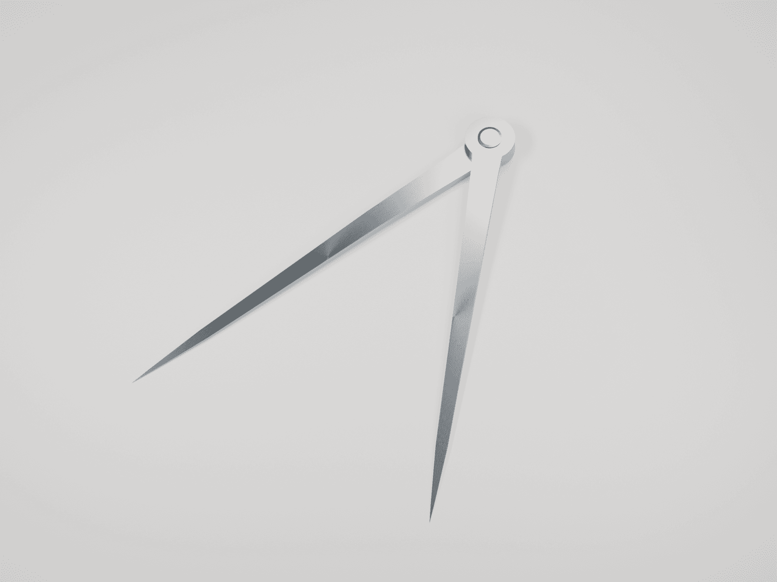
See the intact tool and its features
An original educational poster identifies 4 documented features of this tool. The numbered descriptions remain readable below the artwork on narrow screens.
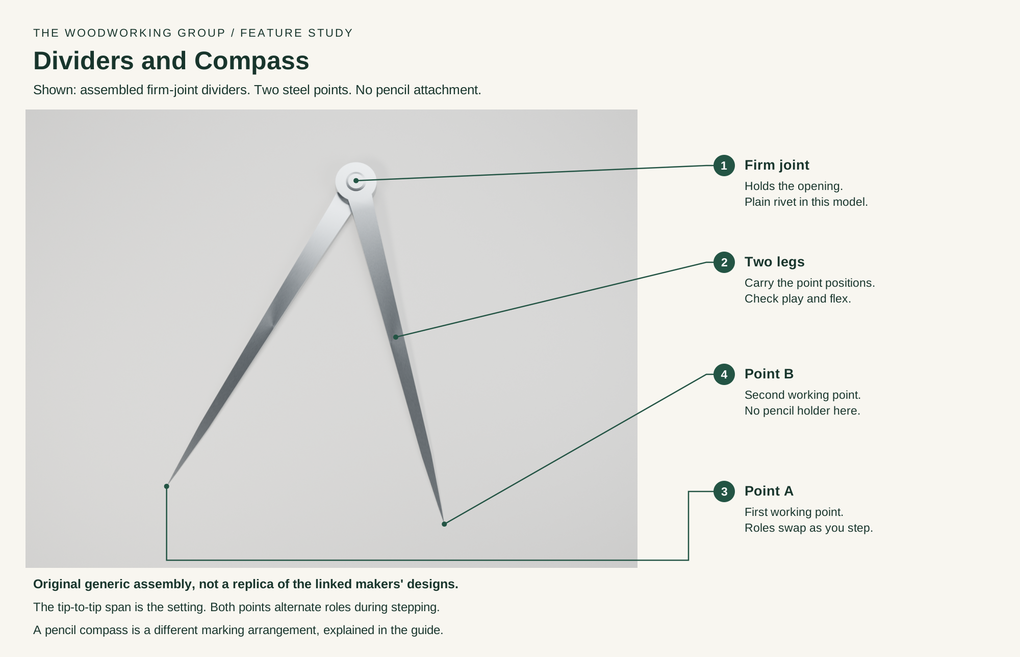
- Firm joint
Friction at the pivot resists a change of setting.
- Two legs
Carry the point positions from the hinge.
- Point A
Registers one end of the transferred span.
- Point B
Registers the other end of the span.
Technical references: Red Rose Reproductions divider design · Starrett 92 carpenter's divider documentation · Why use dividers?. Two tapered steel legs and a plain rivet form this original teaching assembly. The legs overlap at real pivot bores and offset toward a shared tip plane. The six-inch pivot-to-tip length and 44-degree opening are illustration choices, not a capacity claim, model specification or manufacturing plan. Both camera views retain the same assembly. No adjustment screw, spring, wing or pencil holder is depicted. Original educational artwork depicts the intact tool and magnified features; the additional views are not detachable parts.
What it is and what each part does
Dividers hold a distance between two points for comparison, transfer and repeated spacing. They can also scratch arcs where a permanent mark is acceptable. A pencil compass holds a center point and a marking tip to draw arcs or circles. Neither tool reads a dimension by itself, and neither is a cutting tool.
The opening between the working tips is the transferred distance. In the illustrated firm-joint dividers, friction at the hinge resists unintended opening. When stepping along a line, one point becomes the pivot while the other moves to the next position; the roles then swap. A pencil compass instead keeps one center fixed while its pencil traces a radius. Check the setting before and after important work.
1. Firm joint
The two legs overlap at the pivot. This original model uses a plain riveted hinge, not an adjustment screw. Other designs use screws, springs or locking wings; follow their own instructions.
2. Two tapered legs
Carry the tip positions from the hinge to the work. Sideways looseness, bending or excessive opening can make repeated marks unreliable.
3. Point A
Seats lightly on the first reference. In divider stepping it alternates between pivoting and moving; it is not permanently assigned the center role.
4. Point B
Marks or locates the second position. Both divider points must be sound and able to register accurately. A pencil compass replaces one working point with a marking tip in a purpose-made holder.
How the main groups connect
Set, guide and control the action
These decisions make the mechanism useful at the bench.
Preserve the setting
Use enough joint resistance to hold the span without forcing the legs. Adjust only mechanisms intended to be adjusted; do not hammer this illustrated rivet as an operating step.
Choose harmless references
A steel point leaves a puncture or scratch. Mark on an appropriate reference face, waste area or tested protective surface, and consider pencil where permanent marks are unwanted.
Set the actual working tips
Compare the tips to known marks or a suitable rule. On a compass, check the pencil projection, sharpness and clamping before setting the radius.
Transfer a dimension
Take the span directly from a reference or story stick, then locate it on the next part. Keep the same opening and reference convention.
Repeat equal spacing
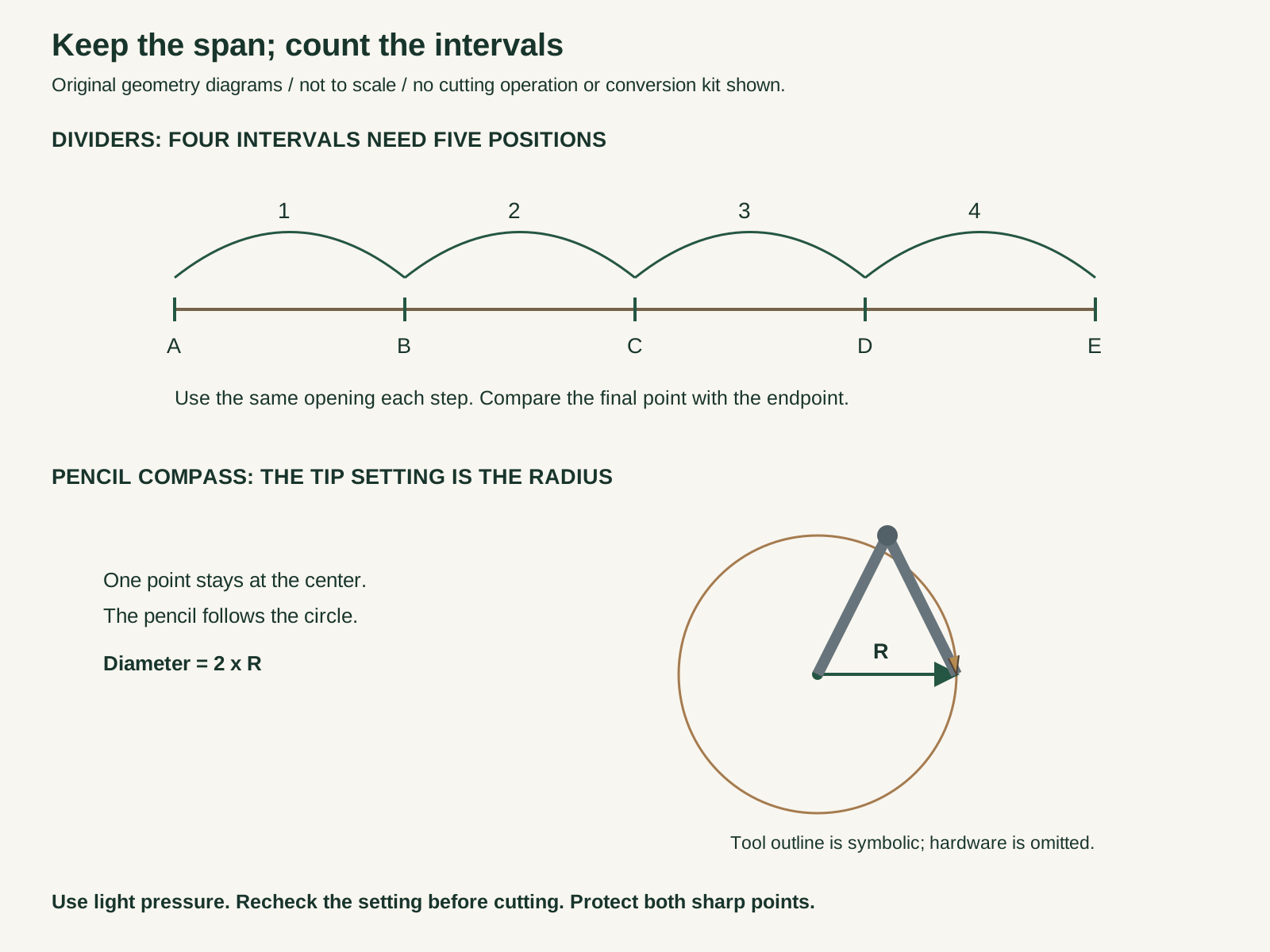
Walk the points along a straight baseline. Count intervals rather than marks, then compare the last step with the intended endpoint.
Lay out circles and arcs
Use a pencil compass for drawn lines or dividers for a deliberate scribed line. Register the center securely and confirm the intended radius.
Plan proportional joinery
Repeated spacing can help organize dovetails or decorative patterns. Joint margins, pin widths and waste still need their own layout method; equal spacing alone does not define a complete joint.
Setup, technique and finish quality
Use the steps for a first pass, then inspect the work before changing the setup.
- Secure the work on a stable surface. Establish the baseline, endpoints and reference faces before making point marks.
- Inspect the joint, legs and tips. Remove debris and check that the setting holds under light working pressure.
- Set the span to the actual tips. For a pencil compass, tighten the intended holder and reset after changing or sharpening the pencil.
- For repeated spacing, place the first point at the start, advance the second along the baseline, then pivot around that new point. Keep the opening unchanged and use light pressure.
- Count the required number of intervals and check the final point against the endpoint. If it misses, adjust the setting and repeat the whole trial from the original start.
- For an arc, locate a stable center, set the radius and make a light trial sweep. Keep the center from wandering and avoid changing the tool angle halfway around.
- Check important marks against the original reference before cutting. Close and protect both points when the layout is complete.
Intervals are not marks
Four equal intervals need five positions when both endpoints are included. In the diagram, A to B is one step; A through E is four steps.
A compass opening is a radius
The distance from the center point to the pencil tip is the radius. A circle diameter is twice that distance, not the tip setting itself.
Small errors accumulate
A loose hinge, sideways lean, thick pencil line or inconsistent point registration can shift the last step. Recheck the endpoint; do not bend the final step to make it look correct.
An arc step is a chord
Walking dividers around a circle marks straight tip-to-tip chords, not lengths measured along the curved arc. Do not apply a straight-line spacing rule blindly to a circle.
What changes by model or material
Quick manual opening held by joint friction. The illustrated tool is a generic riveted version, not a replica of an adjustable modern hinge.
A spring with a screw adjustment or a locking wing can control and retain the setting differently. Do not assume the illustrated plain hinge has either mechanism.
One center point and one pencil or lead holder draw an erasable line. Keep the pencil secure and account for the actual tip, not the holder body.
Some specified dividers accept a pencil attachment; a beam compass or trammels extend the reach. Only use compatible parts and the maker's procedure. The studio dividers do not depict a conversion system.
Choosing the tool
- Choose useful span, joint stability and tip control for the work. Overall leg length is not a guaranteed usable radius or maximum spacing.
- Try repeated light transfers before relying on the tool. Smooth adjustment and a setting that stays put matter more than a decorative finish.
- Choose a marking method that suits the surface. Do not assume that any divider can hold a pencil or that a drafting compass will grip reliably on wood.
Useful accessories
- A clear rule or reference marks for setting a known span
- A story stick or scrap for retaining important settings
- A suitable sharp pencil and compatible compass holder
- Point guards and a protective storage case
Care, troubleshooting and safety
Secure the work, protect sharp edges and release any stored clamping pressure before adjustment or maintenance.
Care checklist
- Wipe the legs and tips clean and dry after use. Prevent corrosion without leaving oil on surfaces that must be glued or finished.
- Protect the points from impact. Replace or dress damaged tips only as the tool design and maker permit; preserve their working alignment.
- Check hinge movement and side play. Use only the specified adjustment or service procedure; forcing, peening or dismantling a joint can damage it.
Common mistakes
- Counting four marks as four intervals when both endpoints are part of the layout.
- Changing the opening during a series of steps or forcing the last point onto the endpoint.
- Setting a compass to the intended diameter instead of the radius.
- Using a deeply scratched line where a removable pencil line was needed.
Safety at the operation
- Keep fingers out of the path of either point. Use light pressure on supported work rather than driving a point toward your hand.
- Close or guard the points for storage and transport. Do not carry exposed points in a pocket or leave the open tool where someone can brush against it.
- Keep dividers and compasses clear of running machinery. Stop and isolate a machine before bringing these layout tools near its work or cutters.
- Do not use the points as a punch, pry bar or cutting tool. A slipping or bent leg can injure you and spoil the layout.
When the result goes wrong
Check the number of intervals, unchanged opening, baseline and point registration. Adjust the span and repeat from the beginning; do not disguise the error in the final step.
Check joint friction or the intended lock, using the manufacturer's procedure. Reduce marking force and look for leg flex or side play.
Check for a moving center, loose pencil, changing tilt or altered opening. Re-establish the radius and make a light trial sweep.
Use less pressure, inspect the point and consider a pencil compass or suitable test surface. A sharp steel point is not an erasable marker.
Look for damage, mismatched projection, dirt or a bent leg. Stop relying on the tool until its intended working alignment is restored.
Manuals and educational resources
Use the exact model documentation for setup, limits and replacement parts. These lessons, documents and model pages teach relevant techniques or help compare real variations.
Manufacturer documentation
Red Rose Reproductions divider design
The maker explains its adjustable friction hinge and removable point construction. Those details are not claimed for this original plain-rivet model.
Starrett 92 carpenter's divider documentation
Manufacturer example with quadrant adjustment, a check nut and a removable point that can accept a pencil. It illustrates a different mechanism, not the geometry shown here.
Learn and compare
Why use dividers?
Lie-Nielsen Australia introduces transfer, repeated spacing and common divider mechanisms.
Compass, dividers and straightedge
Simon St.Laurent discusses the different layout roles and the importance of holding a setting.
Dovetail layout with dividers
Jonathan Katz-Moses presents a joinery-specific layout method. This guide does not replace its separate margin and pin-width decisions.
Friction at the hinge
Lost Art Press describes a feature of its Crucible Type 2 dividers. Its adjustable hardware and setting-recall trick are not features promised by the generic model.
Manufacturers & Brands
These maker-owned links document relevant tools and tool brands. A product brand may use another company's factory; compare the exact model before choosing parts or accessories.
Choose parts for the exact model
Handles, irons, saw plates, clamping pads and other replacements vary by maker and model. Use the maker's documentation before changing a component.
Compare the Layout Tools family →Continue through the Tools library