
Reference/clamping angle
Its short perpendicular leg seats against the same marked face or edge on mating parts. A clean, square registration surface matters more than a nominal board thickness.
Register a drilling guide from one reference face, then bore matching holes for a clean, repeatable dowel joint.
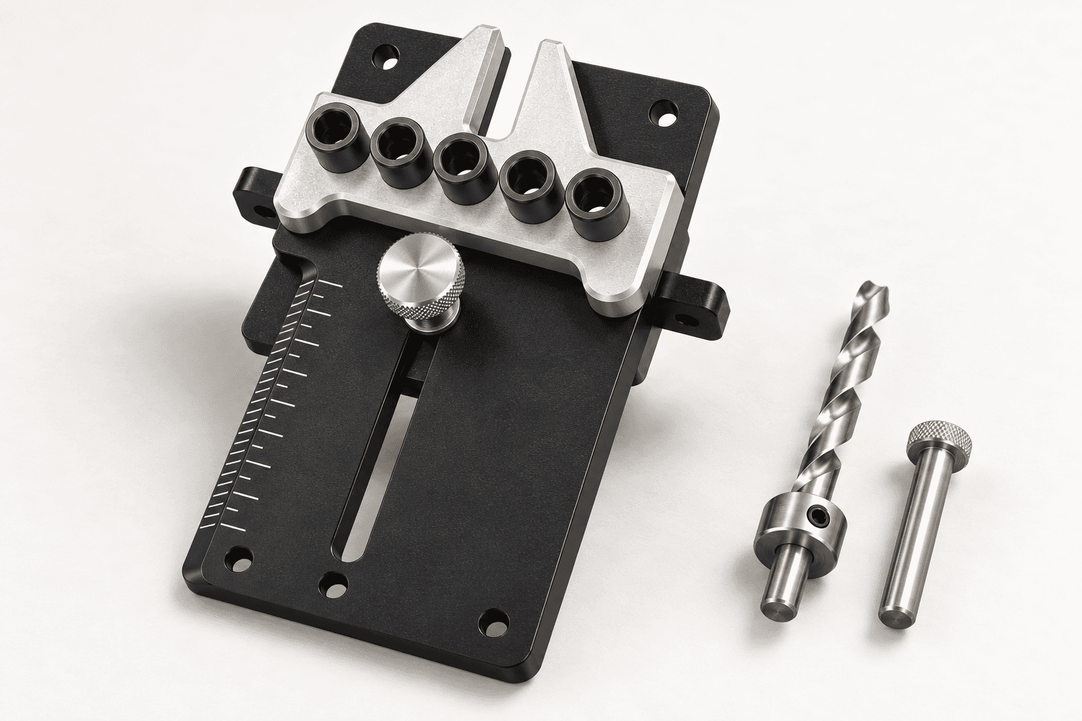
An original educational poster identifies 9 documented construction features. The numbered descriptions remain readable below the artwork on narrow screens.
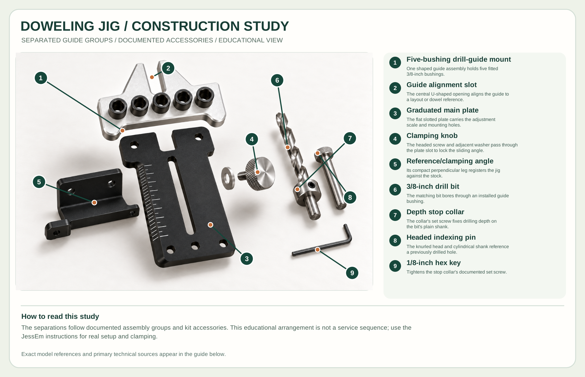
One shaped guide assembly holds five fitted 3/8-inch bushings.
The central U-shaped opening aligns the guide to a layout or dowel reference.
The flat slotted plate carries the adjustment scale and mounting holes.
The headed screw and adjacent washer pass through the plate slot to lock the sliding angle.
Its compact perpendicular leg registers the jig against the stock.
The matching bit bores through an installed guide bushing.
The collar's set screw fixes drilling depth on the bit's plain shank.
The knurled head and cylindrical shank reference a previously drilled hole.
Tightens the stop collar's documented set screw.
Technical references: JessEm 08350 official instructions · JessEm 08350 official product and photos. JessEm's 08350 parts list and assembly drawing identify the five-bushing drill-guide assembly, flat slotted main plate, reference/clamping angle, clamping knob, bit, stop collar, headed indexing pin and hex key. The five bushings remain installed in the guide mount. Original educational artwork depicts documented component groups and their relationships; it is not a service sequence or a replacement for the exact model manual.
A doweling jig controls hole position and drilling angle so paired parts accept dowels. The JessEm 08350 small-jig instructions ground the illustrated guide, bit, depth collar and indexing pin. Other self-centering and edge-reference jigs register differently; transfer a common face rather than assuming their scale settings are interchangeable.
A clamped reference angle establishes the face-to-hole offset. The shaped five-bushing guide mount rides above the flat graduated plate, while the knob locks adjustment through its long slot. Hardened guide bushings constrain a matching bit; the bit's stop collar limits depth. A headed indexing pin can transfer the first hole's spacing to the next location. The separated arrangement is educational and does not prescribe a service sequence.
Its short perpendicular leg seats against the same marked face or edge on mating parts. A clean, square registration surface matters more than a nominal board thickness.
The flat main plate has a long adjustment slot and measurement graduations. The separate shaped mount carries five fitted bushings and a central alignment opening; lock the setting before drilling.
The fitted bushings stay in the guide mount in this study and guide the matching bit. Use the documented size and bit for the selected holes.
The knob and washer secure the selected position through the plate slot. The separate headed pin can register subsequent holes; it is an accessory used during layout, not part of the drilled joint.
The collar limits penetration. Set it for dowel length, glue space and the mating hole depths as directed by the jig manual.
These decisions make the mechanism useful at the bench.
Mark a face and edge on both parts; orient the jig consistently. Flipping one piece to a different reference can misalign the joint.
Set the guide position, tighten the knob, clamp the jig and stock, and verify nothing shifts when the bit enters a bushing.
Set the collar with the maker's method and drill a trial pair. Leave space for glue and confirm the dowels do not bottom out.
Dowels help register board faces during glue-up when holes are indexed from the same reference face.
Paired holes can join rails, stiles and case parts when stock thickness and available edge distance support them.
An indexing pin or carefully marked centerlines can maintain spacing through multiple joints.
Use the steps for a first pass, then inspect the work before changing the setup.
The same reference face makes small stock-thickness differences less likely to create a visible step.
The two blind holes together must accept the dowel with some glue space; a collar set too deep may break through.
Clamping and fence registration still determine location. A loose jig cannot make a straight joint.
Some jigs use fixed rows, others shift a guide body or self-center between jaws. Follow the exact registration scheme supplied.
Choose diameter, spacing and number for available stock, grain direction and joint load; avoid crowding a thin edge.
Blind holes hide the dowel; through holes expose it and require different depth and finish planning.
Secure the work, protect sharp edges and release any stored clamping pressure before adjustment or maintenance.
Recheck common reference faces, fence seating and guide lock.
Check bit diameter, hole depth, chips and dowel size; do not force glue into a blind bottom.
Inspect bushing fit, bit sharpness, clamping and drilling pressure.
Use the exact model documentation for setup, limits and replacement parts. These lessons, documents and model pages teach relevant techniques or help compare real variations.
These maker-owned links document relevant tools and tool brands. A product brand may use another company's factory; compare the exact model before choosing parts or accessories.
Handles, irons, saw plates, clamping pads and other replacements vary by maker and model. Use the maker's documentation before changing a component.
Compare the Joinery family →Continue through the Tools library