
Cast base and fixed jaw
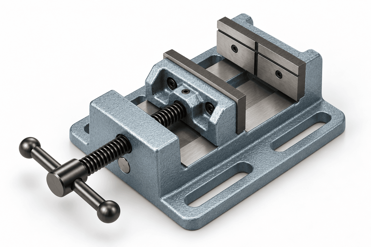
The rear jaw is integral with the slotted base; its four elongated mounting slots provide table-bolt positions.
Hold a small workpiece against drill torque with a bolted low-profile vise, aligned jaws and a single lead screw.
An original educational poster identifies 7 documented construction features. The numbered descriptions remain readable below the artwork on narrow screens.
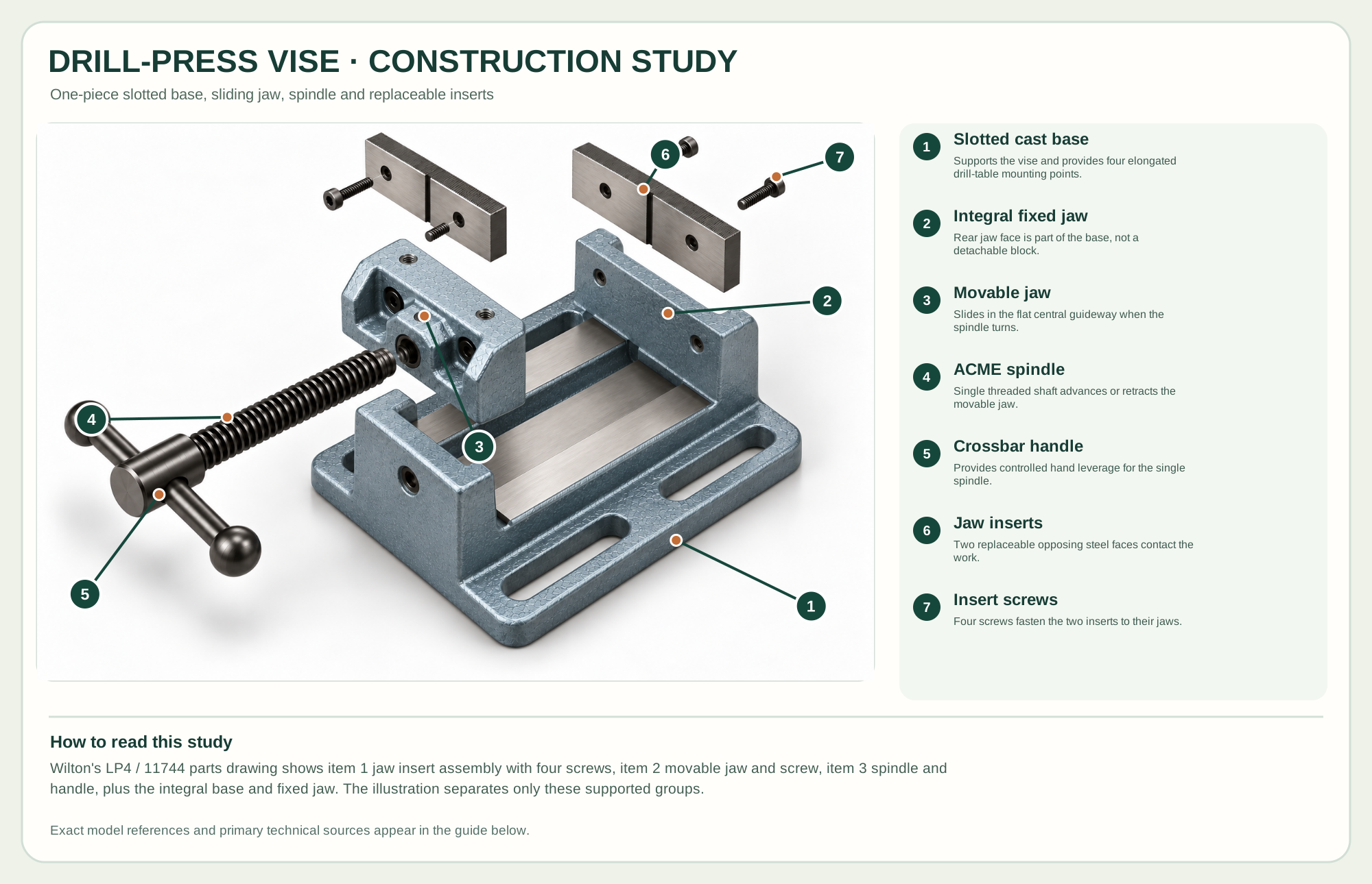
Supports the vise and provides four elongated drill-table mounting points.
Rear jaw face is part of the base, not a detachable block.
Slides in the flat central guideway when the spindle turns.
Single threaded shaft advances or retracts the movable jaw.
Provides controlled hand leverage for the single spindle.
Two replaceable opposing steel faces contact the work.
Four screws fasten the two inserts to their jaws.
Technical references: Wilton LP4 / 11744 official parts diagram · Wilton LP4 product. A single ACME spindle advances the moving jaw along a flat cast-base slideway toward the fixed jaw. The fixed jaw and slotted base are one casting. Two replaceable steel inserts attach to facing jaws with four screws. No extra guide rods are part of the official assembly. Original educational artwork depicts documented component groups and their relationships; it is not a service sequence or a replacement for the exact model manual.
Wilton's LP4 stock 11744 is a four-inch low-profile drill-press vise with a slotted cast base, fixed rear jaw, movable jaw and a single ACME spindle with crossbar handle. Its four mounting points let the vise be secured to a drill-press table. It holds small work for boring, but a drill-press vise still needs proper bolting or clamping; hand pressure alone cannot resist snagging torque.
The cast base and fixed jaw form one structure. Turning the single ACME spindle moves the front jaw along the flat slideway toward or away from the fixed jaw. Replaceable jaw inserts fasten to opposing faces with two screws each. The official three-item parts diagram identifies a jaw-insert assembly, movable jaw with its retaining screw, and spindle-and-handle assembly; the poster shows these actual connections rather than invented guide rods.
The rear jaw is integral with the slotted base; its four elongated mounting slots provide table-bolt positions.
A single cast jaw travels along the base's flat channel; keep bearing surfaces clean and parallel.
One central threaded spindle advances the movable jaw; the crossbar offers controlled hand torque.
Steel inserts fasten to the opposing jaw faces; inspect both surfaces and screws before clamping wood.
These decisions make the mechanism useful at the bench.
Use suitable table slots or a compatible clamp arrangement that prevents the vise from rotating under drilling torque.
Place flat stock low between parallel jaws; use sacrificial pads when marks matter and support long pieces separately.
Turn the drill by hand to confirm the bit clears jaws, base and mounting hardware before power.
Use a table stop and securely clamped work for a small run of identical parts.
Keep fingers out of the bit area while the vise restrains a piece too small to hold safely by hand.
Use a purpose-made V-block or jaw pads where the shape permits safe bearing and clamping.
Use the steps for a first pass, then inspect the work before changing the setup.
The model uses a central screw and flat slideway; extra parallel guide rods are not part of its documented construction.
An unsecured vise can spin with the drill; positive mounting is part of the setup.
It is part of the base in the official drawing; only the documented jaw inserts and moving assembly separate in the study.
Size the vise for the stock, while leaving clearance for the drill and table.
A shorter vise preserves drill-press quill travel compared with taller machine vises.
Soft pads protect wood but can change grip and opening; use them only with stable contact.
Secure the work, protect sharp edges and release any stored clamping pressure before adjustment or maintenance.
Remove chips from slideway and inspect a bent spindle or damaged bearing surfaces.
Inspect insert faces, work shape, clamping height and mounting security.
Check punch/center location, bit sharpness, quill play and stock support rather than simply increasing jaw force.
Use the exact model documentation for setup, limits and replacement parts. These lessons, documents and model pages teach relevant techniques or help compare real variations.
These maker-owned links document relevant tools and tool brands. A product brand may use another company's factory; compare the exact model before choosing parts or accessories.
Handles, irons, saw plates, clamping pads and other replacements vary by maker and model. Use the maker's documentation before changing a component.
Compare the Woodworking Vises family →Continue through the Tools library