
Black iron pipe
Use the correct 3/4-inch threaded black pipe; it is purchased separately and sets maximum clamping span.
Use a sliding clutch jaw and screw-driven head on a separately chosen black pipe for long-panel glue-ups.
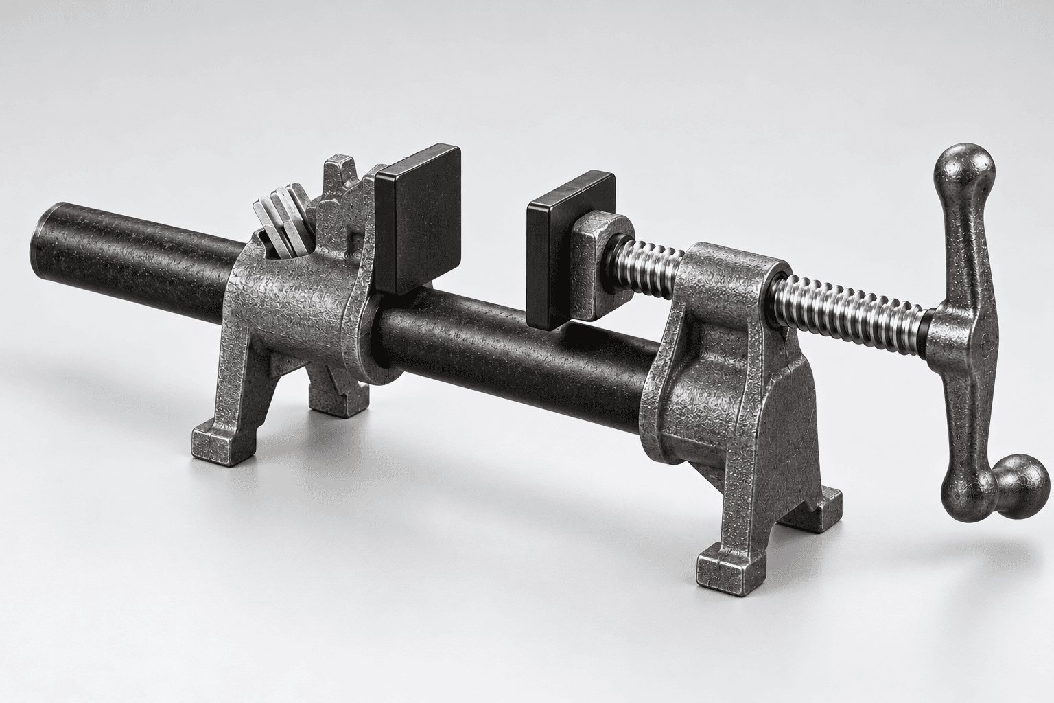
An original educational poster identifies 9 documented construction features. The numbered descriptions remain readable below the artwork on narrow screens.
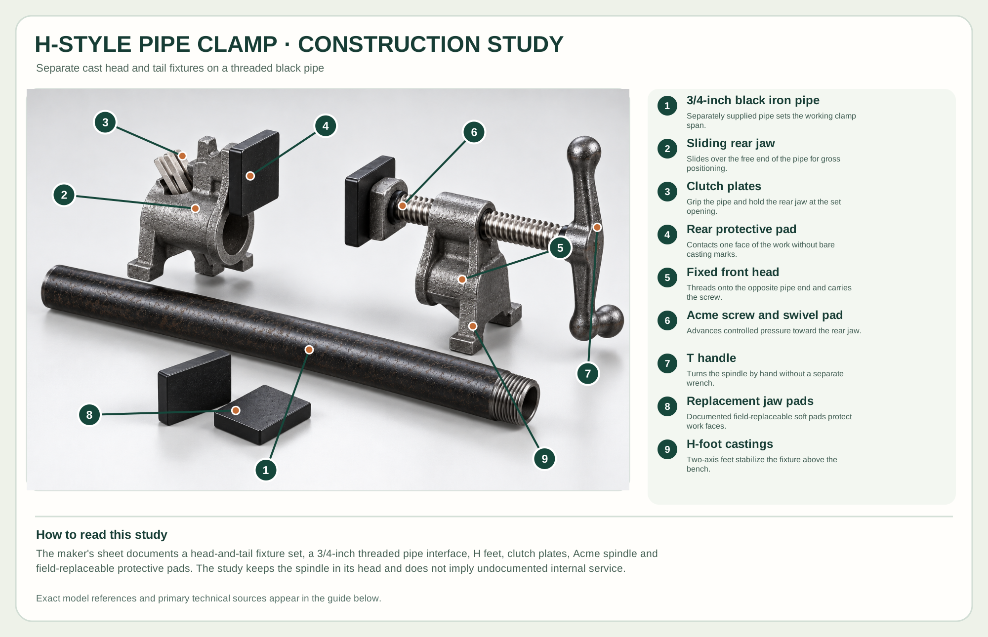
Separately supplied pipe sets the working clamp span.
Slides over the free end of the pipe for gross positioning.
Grip the pipe and hold the rear jaw at the set opening.
Contacts one face of the work without bare casting marks.
Threads onto the opposite pipe end and carries the screw.
Advances controlled pressure toward the rear jaw.
Turns the spindle by hand without a separate wrench.
Documented field-replaceable soft pads protect work faces.
Two-axis feet stabilize the fixture above the bench.
Technical references: BESSEY official pipe-clamp technical sheet. The sliding rear jaw enters from the pipe's free end and grips it with clutch plates. The fixed front head threads onto the opposite end; its Acme screw advances a swiveling pad toward the rear pad. The black iron pipe is separately purchased and cut to working length. Original educational artwork depicts documented component groups and their relationships; it is not a service sequence or a replacement for the exact model manual.
BESSEY's BPC-H34 is a pair of high H-style clamp fixtures for a separately supplied 3/4-inch threaded black iron pipe. The official sheet identifies a sliding rear jaw with clutch plates, a fixed front head that screws onto the pipe, a smooth-action Acme spindle, soft replaceable pads and broad feet. Pipe length determines overall opening; the head-and-tail fixture set itself is not a pre-sized bar clamp. The original illustration uses neutral graphite castings rather than manufacturer color or marks.
The rear jaw slides over the free pipe end; its clutch plates bite when pressure is applied. The front head threads onto the opposite pipe end and carries the Acme screw. Turning the T handle advances a swiveling pressure pad toward the rear pad. H feet keep both castings elevated and stable on a bench. The study separates each complete jaw fixture from the continuous pipe and shows spare pads; it does not dismantle the front spindle or clutch stack.
Use the correct 3/4-inch threaded black pipe; it is purchased separately and sets maximum clamping span.
A plate stack grips the pipe in one direction and releases for gross repositioning when the maker's control is operated.
The front head attaches at the threaded pipe end. A screw and T handle develop controlled closing force.
Field-replaceable soft pads protect the work, while the broad two-axis feet give bench clearance.
These decisions make the mechanism useful at the bench.
Use a straight, sound black iron pipe with clean matching threads; check the pipe and clamp maker's specifications.
Slide it near the work, then test that the clutch plates engage before increasing screw pressure.
Use several clamps with alternating directions on a panel and tighten only enough to close the joint.
Distribute H-style clamps along the panel and use cauls or protective pads as the stock requires.
Support the frame square and apply controlled pressure along joint lines without bowing rails.
A chosen pipe length reaches a span beyond short bar clamps; support long pipe ends so the work stays level.
Use the steps for a first pass, then inspect the work before changing the setup.
The clamp kit's working length is determined by a separately chosen threaded pipe.
The rear plates set a rough position; the front Acme spindle develops the final force.
The maker lists replacement soft pads; worn bare cast faces can mark work.
BPC-H12 uses a different pipe size; do not interchange its fixtures with a BPC-H34 pipe.
Longer pipe increases reach but can add flex and requires support during glue-up.
Field-replaceable soft pads protect finished surfaces; supplementary cauls spread force on delicate work.
Secure the work, protect sharp edges and release any stored clamping pressure before adjustment or maintenance.
Remove load; inspect clutch plates, pipe surface and correct orientation before reuse.
Back off, clean dried glue and inspect spindle/thread damage; do not force it.
Reduce pressure and distribute clamps on both faces with suitable cauls and support.
Use the exact model documentation for setup, limits and replacement parts. These lessons, documents and model pages teach relevant techniques or help compare real variations.
These maker-owned links document relevant tools and tool brands. A product brand may use another company's factory; compare the exact model before choosing parts or accessories.
Handles, irons, saw plates, clamping pads and other replacements vary by maker and model. Use the maker's documentation before changing a component.
Compare the Woodworking Clamps family →Continue through the Tools library