
Sliding guide head and spindle
The cast head supports the rotating spindle on bearings while its two bushings track the parallel guide bars. The drill attaches to the upper shaft, not to the lower chuck.
Guide a handheld drill at repeatable angles and depths where a drill press cannot reach.
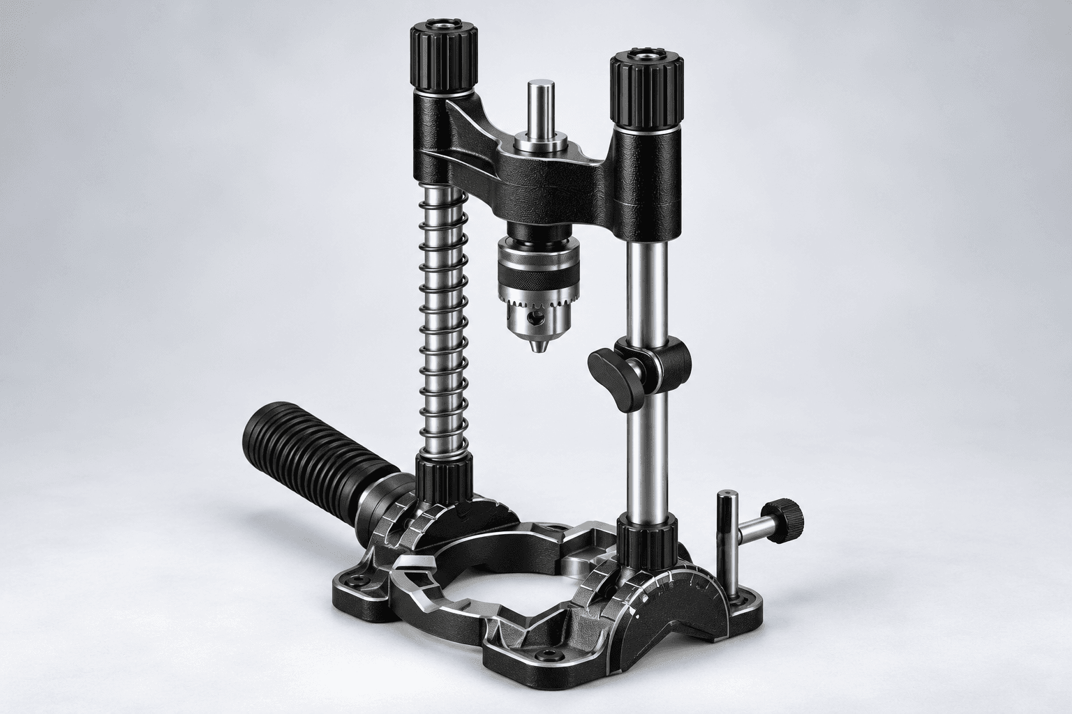
An original educational poster identifies 9 documented construction features. The numbered descriptions remain readable below the artwork on narrow screens.
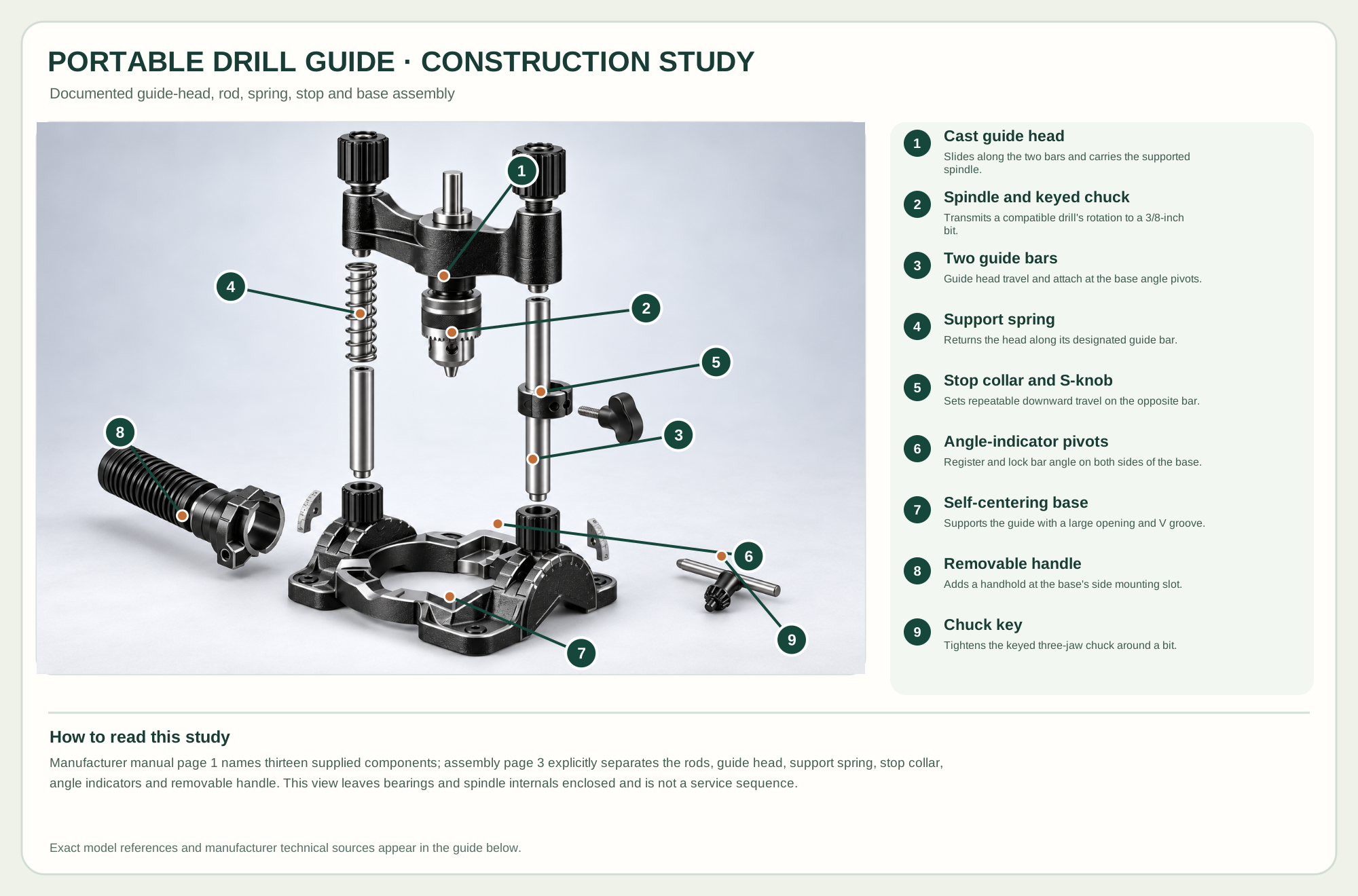
Slides along the two bars and carries the supported spindle.
Transmits a compatible drill's rotation to a 3/8-inch bit.
Guide head travel and attach at the base angle pivots.
Returns the head along its designated guide bar.
Sets repeatable downward travel on the opposite bar.
Register and lock bar angle on both sides of the base.
Supports the guide with a large opening and V groove.
Adds a handhold at the base's side mounting slot.
Tightens the keyed three-jaw chuck around a bit.
Technical references: Milescraft 1318 official product · Milescraft 1318 instruction manual, M1318MRV4. The 1318 guide head slides on two bars. One bar carries the return spring and the other the adjustable depth-stop collar. Their lower ends fasten at the two base angle pivots; the keyed chuck stays attached to the spindle-head group in this educational arrangement. Original educational artwork depicts documented component groups and their relationships; it is not a service sequence or a replacement for the exact model manual.
Milescraft's 1318 DrillMate is a portable guide for a compatible 3/8- or 1/2-inch handheld drill, not a powered drill press. The drill grips the guide's upper spindle; the guide's 3/8-inch keyed chuck holds the bit. Its cast base has a central opening, V groove, nonslip feet and angle readouts. Two steel bars carry the guide head, with a support spring on one side and a depth stop on the other. This original unbranded artwork follows the manufacturer's 2023 manual revision 4; the drill motor is separate and is not drawn as part of the guide.
As the operator feeds the attached drill, the head travels down both bars and turns a bit in the guide's lower chuck. The single spring returns the head. A collar limits repeated travel; the two bar feet pivot at matching angle indicators and lock at a chosen setting. The construction study separates the exact bar, spring, stop, indicator and handle groups described in the maker's assembly instructions while leaving the enclosed head bearings intact. It is an educational arrangement, not a repair sequence.
The cast head supports the rotating spindle on bearings while its two bushings track the parallel guide bars. The drill attaches to the upper shaft, not to the lower chuck.
A 3/8-inch keyed three-jaw chuck holds a compatible drill bit; remove the key before starting the drill.
The one spring and opposite adjustable collar serve different functions. The manual places them on separate rods during assembly.
Two angle indicators help align the pivoting bars; a removable side handle helps steady the base. The central opening and V groove register flat or round stock.
These decisions make the mechanism useful at the bench.
With power disconnected, tighten the handheld drill's chuck on the guide's upper spindle and fit a suitable bit in the guide's lower keyed chuck.
Loosen both angle locks, set matching graduations, retighten, and set the stop collar against the head for the intended depth.
Clamp the work. On broad or large-hole work, restrain the guide base; keep the handle and bit clear of obstructions.
Use the 90-degree setting and a flat registered base for repeatable holes away from a drill press.
Match both side scales at a documented angle and make a scrap trial to check entry position and breakthrough.
Seat the V groove on clamped cylindrical stock so the guide does not roll as the bit enters.
Use the steps for a first pass, then inspect the work before changing the setup.
The attached handheld drill turns the spindle. The accessory should not be represented as a self-powered machine.
A short bit or a large Forstner cutter may need spring removal for clearance, as Milescraft's FAQ explains. Recheck travel before drilling.
Set both sides identically and verify the actual bore in scrap rather than assuming graduations alone guarantee an exact angle.
The spring returns the head after a straight guided feed.
Both rod pivots tilt and lock together; a longer bit may be needed for base clearance.
The 1318 has a spindle and lower chuck for common U.S. drills; the 1368 holds a 43-mm European drill collar and is a distinct model.
Stop the tool and disconnect power before investigating a fault or changing a part.
Check both angle indicators, pivot locks, base seating, rod straightness and bit sharpness.
Clean the bars and head bushings; inspect the spring and use only the maker-recommended light lubricant.
Verify bit length and whether spring or stop limits travel; follow the manual before removing the spring.
Use the exact tool manual for setup, limits and replacement parts. These lessons, documents and model pages teach relevant techniques or help compare real variations.
These maker-owned links document relevant tools and tool brands. A product brand may use another company's factory; compare the exact model before choosing parts or accessories.
Cutters, abrasives, guards, guides, dust fittings and service parts vary by tool. Check the model plate and manufacturer manual before ordering or changing a component.
Compare the Drilling family →Continue through the Tools library