
Table Saw Tapering Jig
Set and repeat a controlled taper while keeping stock registered against a dedicated jig.
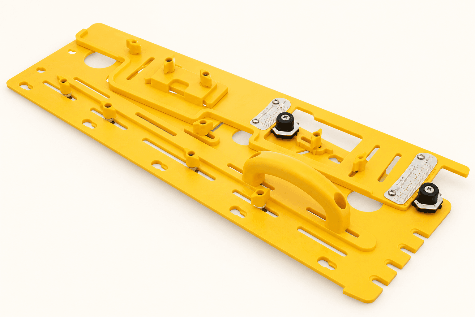
See the assembled tool and its components
An original educational poster identifies 9 documented construction features. The numbered descriptions remain readable below the artwork on narrow screens.
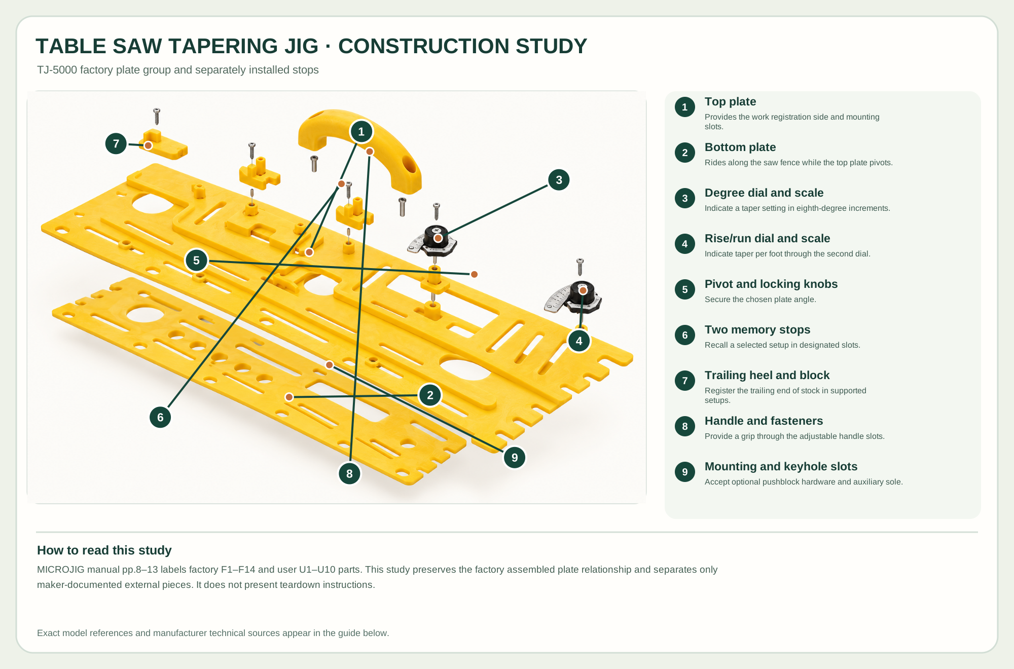
- Top plate
Provides the work registration side and mounting slots.
- Bottom plate
Rides along the saw fence while the top plate pivots.
- Degree dial and scale
Indicate a taper setting in eighth-degree increments.
- Rise/run dial and scale
Indicate taper per foot through the second dial.
- Pivot and locking knobs
Secure the chosen plate angle.
- Two memory stops
Recall a selected setup in designated slots.
- Trailing heel and block
Register the trailing end of stock in supported setups.
- Handle and fasteners
Provide a grip through the adjustable handle slots.
- Mounting and keyhole slots
Accept optional pushblock hardware and auxiliary sole.
Technical references: MICROJIG TJ-5000 product · MICROJIG official instruction manual v7.0. The top and bottom plates pivot relative to each other at the joint. The degree and rise/run scales indicate that pivot, while locking and pivot knobs hold the setup. Memory stops, a trailing heel and handle mount in plate slots. GRR-RIPPER pushblocks are compatible accessories sold separately, not included in the jig. Original educational artwork depicts documented component groups and their relationships; it is not a service sequence or a replacement for the exact model manual.
What it is and what each part does
The MICROJIG TJ-5000 MICRODIAL is a wide, low-profile table-saw tapering jig built from a factory-assembled top and bottom plate. It is not the older hinged two-stick taper guide. Two maker-marked scales express the setting in degrees or rise per foot; the manual specifies 0–10 degrees and 0–2 inches per foot, with eighth-degree and sixteenth-inch-per-foot indexed settings. The yellow handle, two MEMORYLOCK stops and trailing block are user-installed parts. Compatible GRR-RIPPER pushblocks and an optional auxiliary sole are separate accessories, not included pushblocks.
The top plate pivots relative to the bottom plate, creating a wedge that carries the stock through a tapering pass while the bottom edge follows a properly set parallel rip fence. The degree and rise/run MICRODIALs register the chosen angle; pivot and locking knobs hold it. A trailing heel keeps the workpiece from slipping rearward, and the memory stops recall settings. The maker's diagram identifies F1–F14 factory parts and U1–U10 user-installed parts, so the construction study preserves the plate relationship and separates only documented external groups.
Factory top and bottom plates
Long yellow plates provide the work edge and fence-following edge. Their pivot changes the taper angle.
Two MICRODIAL systems
One indicates degrees, the other rise/run per foot. Release the scales from their pins before repositioning to avoid damage.
Pivot and locking knobs
Both must be tight before cutting; the dial setting alone does not lock the jig.
Trailing heel and memory stops
The trailing block registers stock and the two adjustable stops recall positions in the intended slots.
Handle and mounting slots
A yellow handle mounts with its supplied hardware. Slots permit documented pushblock hardware; the pushblocks themselves are sold separately.
How the main groups connect
The two plates set the taper
Set, guide and control the action
These decisions make the mechanism useful at the bench.
Choose a taper
Mark the desired taper on scrap; use the maker's degree dial or calculate rise × 12 ÷ run for inches per foot.
Set and lock
Lift dials to disengage the pins, pivot to the documented mark, then tighten both pivot and locking knobs.
Register stock
Seat the work against the jig fence and trailing heel; plan full support, a safe push method and saw-fence position.
Tapered furniture leg
Lay out the taper, set the appropriate angle and make a scrap pass to check the bottom and top widths.
Straight-edge jointing pass
The manual describes trailing-block slots for a jointing configuration; confirm the exact setup before using that mode.
Repeated taper
Use both MEMORYLOCK stops to recall a previously established layout, then confirm the cut with a measurement.
Setup, technique and finish quality
Use the steps for a first pass, then inspect the work before changing the setup.
- Read the TJ-5000 and table-saw manuals; unplug the saw for initial setup and dry run.
- Install the supplied handle, two memory stops and trailing block using the correct slots and hardware.
- Lay out the taper; use the degree scale or calculate rise per foot from rise × 12 ÷ run.
- Lift each MICRODIAL off its indexing pin before changing angle; never force a scale against its pin.
- Set the chosen angle, tighten pivot and locking knobs, and verify the fence is parallel to the blade.
- Seat stock firmly against the jig's work edge and trailing heel; use compatible hold-down or pushblocks as instructed.
- With the blade lowered and saw unplugged, rehearse the whole pass; then make a scrap cut and check dimensions before production pieces.
Degrees and rise/run are different units
The two dials describe the same plate pivot in different ways. A 3/8-inch taper over 18 inches, for example, is 1/4 inch per foot, as the manual demonstrates.
A dial is an index, not a clamp
The scale pin locates an increment. Both locking and pivot knobs must be secured before the jig is pushed through the saw.
Pushblocks are separate
The maker provides hardware and slots for compatible GRR-RIPPER models but states that the pushblocks are not included.
What changes by model or material
Index 0–10 degrees in eighth-degree steps using the manual's color-matched scale.
Index 0–2 inches per foot in sixteenth-inch-per-foot steps; use an unpinned setting only after independent verification.
Maker-provided keyholes accept an optional user-made sole; its screws and material are not included.
Choosing the tool
- Check the required taper angle and stock length against the TJ-5000's range and plate size.
- Confirm the table saw and rip fence can maintain support through the full cut.
- Budget separately for compatible GRR-RIPPER pushblocks if that holding method is needed.
Useful accessories
- Compatible table saw and rip fence
- Optional separately sold GRR-RIPPER pushblocks
- Optional user-made auxiliary sole
- Supplied handle, heel and memory stops
Consumables
- Scrap stock for taper tests
- Appropriate sharp table-saw blade
Care, troubleshooting and safety
Stop the tool and disconnect power before investigating a fault or changing a part.
Care checklist
- Clean sawdust from slots, dial pins and plate pivot.
- Inspect the two locking knobs, stop fasteners and heel before use.
- Protect scale markers from impacts; store the jig flat.
- Replace only compatible hardware from the maker's list.
Common mistakes
- Trying to rotate either dial with its indexing pin engaged.
- Cutting with a loose pivot or locking knob.
- Failing to seat stock against the heel.
- Describing separately sold pushblocks as part of the supplied jig.
Safety at the operation
- Unplug the saw and lower the blade for a complete dry run of the intended setup.
- Use the maker's documented workholding and table-saw guarding instructions.
- Keep fingers and the jig body clear of blade travel and plan the exit path.
- Do not force a binding workpiece or proceed with a loose fence, heel or knob.
When the result goes wrong
Recheck degrees versus rise/run, dial pin engagement, measured run length, fence parallelism and scrap layout.
Check heel location, work-edge registration, hold-down and both locked knobs.
Lift to disengage its pin and clean the scale; do not force the knob.
Manuals and educational resources
Use the exact tool manual for setup, limits and replacement parts. These lessons, documents and model pages teach relevant techniques or help compare real variations.
Manufacturer manuals
Learn and compare
Manufacturers & Brands
These maker-owned links document relevant tools and tool brands. A product brand may use another company's factory; compare the exact model before choosing parts or accessories.
Choose parts for the exact model
Cutters, abrasives, guards, guides, dust fittings and service parts vary by tool. Check the model plate and manufacturer manual before ordering or changing a component.
Compare the Joinery family →Continue through the Tools library