
Handscrew Clamp
Use two independently adjusted screws and broad wooden jaws to hold small, tapered or awkward work with controlled contact.
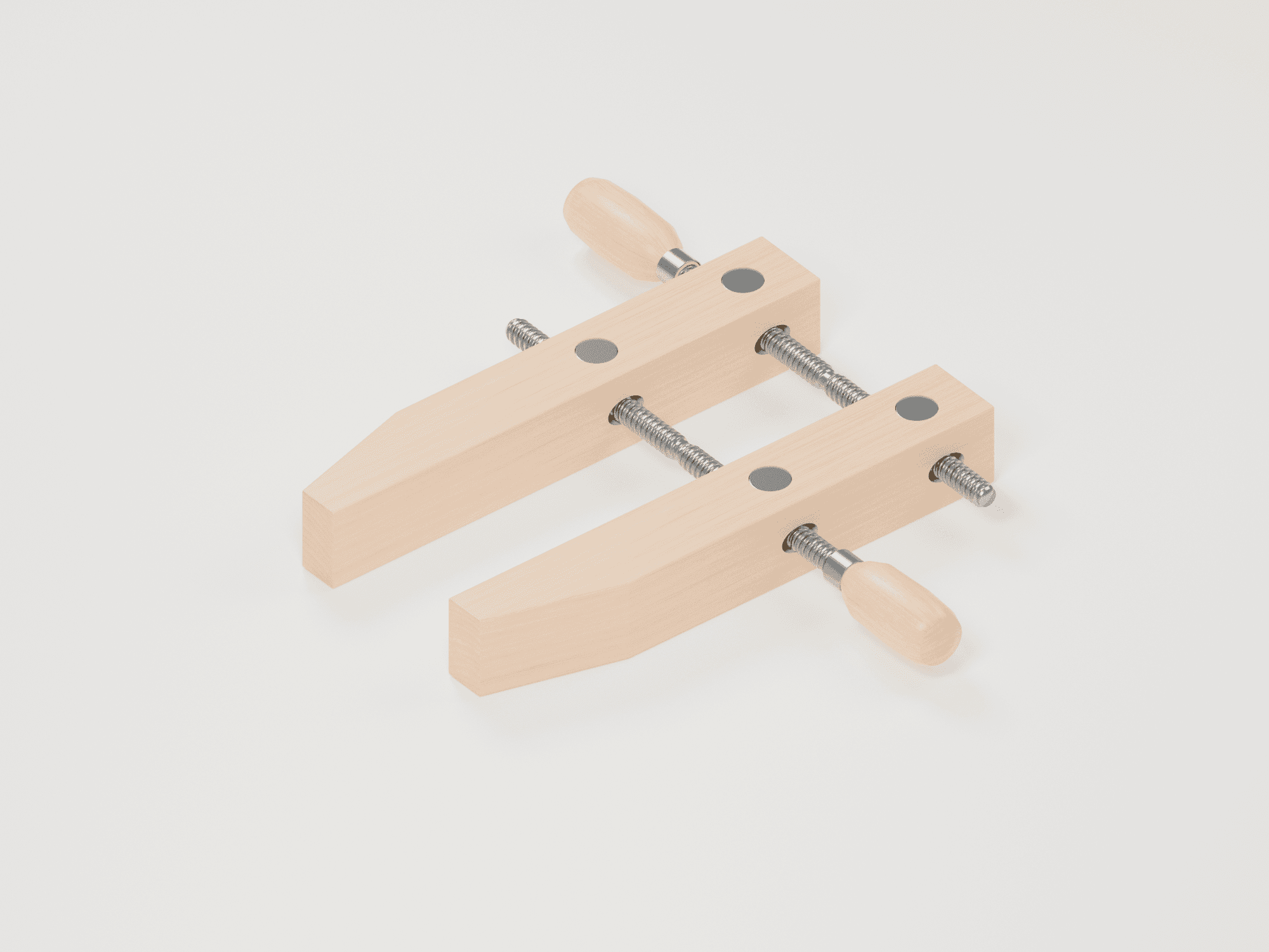
See the assembled tool and its components
An original educational poster identifies 5 documented construction features. The numbered descriptions remain readable below the artwork on narrow screens.
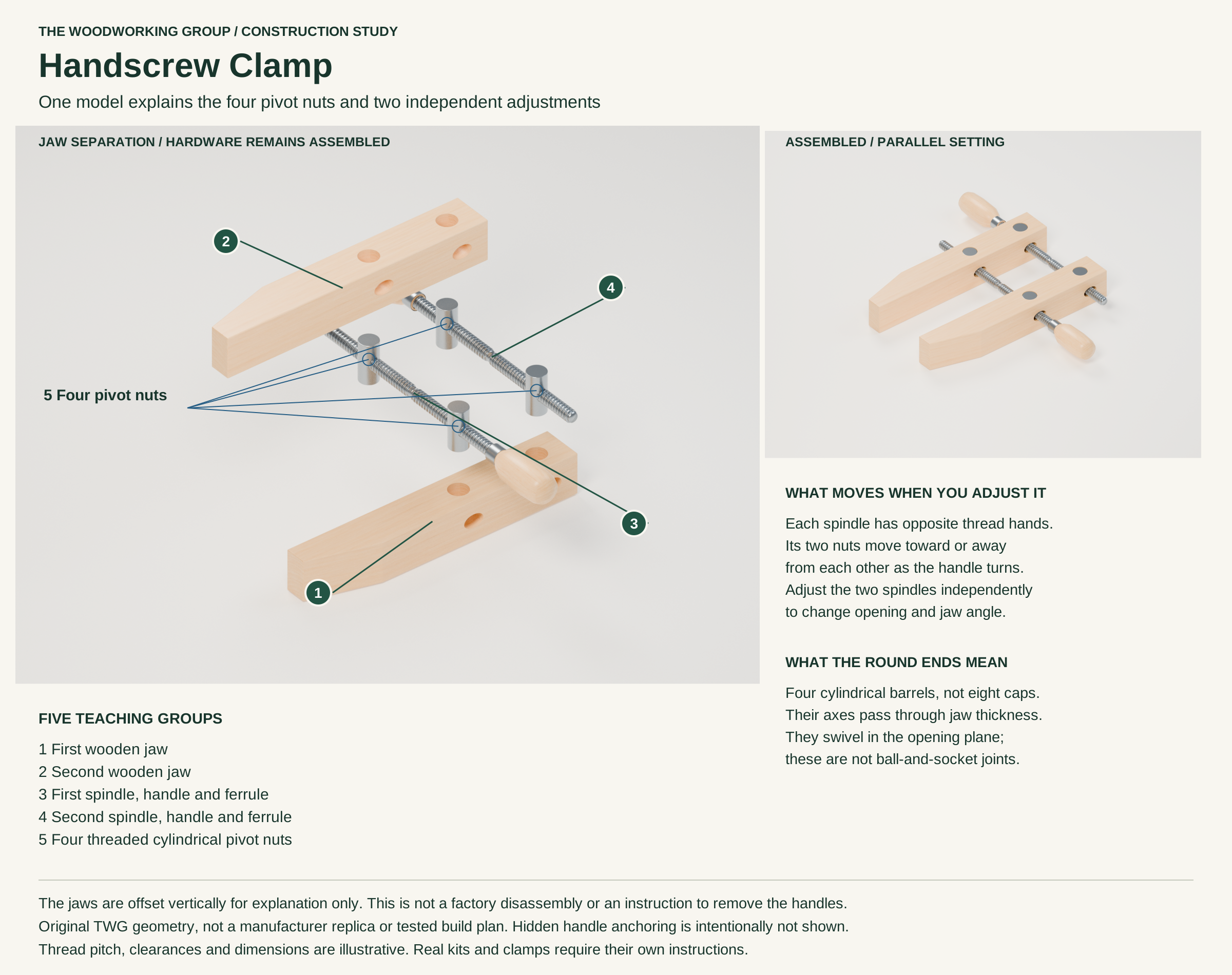
- First wooden jaw
One broad inner face contacts the work. Two cylindrical seats carry its pivot nuts.
- Second wooden jaw
Opposes the first jaw. Its two spindle settings establish opening and angle together.
- First spindle and handle assembly
Opposite thread hands on one shaft move its two nuts toward or away from each other. The handle and ferrule remain assembled.
- Second spindle and handle assembly
Independent adjustment changes the spacing at the other spindle. Its handle is on the opposite side in this arrangement.
- Four pivot nuts
One cylindrical nut at each jaw and spindle intersection. Transverse swivel axes permit jaw-angle changes.
Technical references: BESSEY product sheet · Taytools kit contents · Woodsmith mechanism explanation. The two wooden jaws are displaced vertically only to expose the four barrel nuts. All steel, handles and ferrules remain in the same assembled relationship. This is an explanatory separation, not a service sequence. Hidden handle anchoring is intentionally not depicted; the model is not a manufacturer replica or a build plan. This original construction is for teaching, not a tested build plan, manufacturer replica or service sequence.
What it is and what each part does
A handscrew changes both its opening and the angle between its jaws. Unlike a bar clamp, it has no sliding rail or single moving pressure pad. Its broad jaws can spread contact and can themselves be secured in a suitable vise or fixture. Wood does not guarantee mark-free holding: grit, limited contact and excessive pressure can still damage the work.
Each steel spindle passes through a cylindrical nut in each jaw. Opposite thread hands on the two portions of that spindle move its nuts toward or away from each other. The cylindrical nuts can swivel around their transverse axes as the jaws change angle. Adjusting both spindles together changes the opening; adjusting them by different amounts changes the jaw angle. The illustrated hardware is a generic explanation of this mechanism, not a factory parts drawing.
Two wooden jaws
The inner faces contact the work. The noses reach beyond the nearer spindle, while the thicker rear sections house the pivot nuts. Keep those faces clean and check the wood around every socket.
Two spindle assemblies
Each handle turns one threaded spindle. The handles are on opposite sides in the pictured arrangement. The spindle lengths differ in this original example; real lengths and travel depend on the model.
Four cylindrical pivot nuts
There is one nut at each spindle-to-jaw intersection. A nut rotates about the axis through the jaw thickness; it is not a ball joint. The visible round ends belong to four barrels, not separate caps.
Ferrules and retained handles
A metal ferrule surrounds each handle neck. The illustration keeps each handle assembly intact. It does not show a handle-removal sequence or prescribe hidden anchoring hardware.
How the main groups connect
Set, guide and control the action
These decisions make the mechanism useful at the bench.
Start with parallel faces
Open the clamp enough for the work, then bring the two jaws close to parallel. Begin with broad, stable contact instead of forcing one tip into a finished surface.
Adjust one spindle at a time
Use small hand adjustments and watch both contact areas. A change at one screw can alter the jaw angle as well as local clearance.
Seat a taper deliberately
For a tapered part, adjust the jaws to follow the intended contact faces. Check that the part cannot slide out as pressure increases; use a different fixture if contact remains unstable.
Small hand-tool work
Hold a manageable part in the wooden jaws, then secure the clamp itself when the operation needs a fixed support. Keep the cutting path clear of wood, steel and fingers.
Local glue-up alignment
Use broad, clean faces to help align a small joint or local panel edge. A handscrew does not replace a complete clamping plan for a large assembly.
Tapered or awkward shapes
Independent adjustment can accommodate a non-parallel contact. Curved or fragile parts may need shaped cauls or a purpose-made fixture rather than more pressure.
Setup, technique and finish quality
Use the steps for a first pass, then inspect the work before changing the setup.
- Inspect both jaws, four nut seats, spindles, handles and contact faces. Set aside a cracked, bent or loose clamp.
- Choose opening and throat reach for the actual work. Rehearse the clamp and tool positions before applying pressure.
- Set the jaws approximately parallel and seat the part against sound contact areas. Add suitable clean protection if needed.
- Turn the handles in small increments, adjusting each spindle to maintain the intended contact. Keep fingers clear of closing gaps.
- Tighten by hand only, then check for slip or rocking. Do not add a pipe, wrench or impact to gain force.
- If the operation needs fixed workholding, secure the clamp itself in an appropriate fixture and check the entire setup before starting.
- Release pressure in a controlled way while supporting the work. Remove the clamp when the temporary holding job is complete.
Thread hand is not a universal turning instruction
The direction that closes a gap depends on which handle end you are viewing and how the threads are arranged. Observe the jaws during a light adjustment instead of relying on an unexplained clockwise rule.
Jaw angle comes from two settings
There is no separate angle-lock knob. Unequal spindle adjustments establish the relationship between the jaws; the pivot nuts allow those changes without turning the wooden jaws into threaded nuts.
Holding a clamp is another workholding problem
A clamp gripping a part can still move as a whole. A vise or secondary fixture must suit the forces of the operation. This page does not certify a setup for powered cutting or drilling.
What changes by model or material
Jaw length is not the same measurement as opening or throat depth. Compare the exact maker table rather than carrying one brand’s dimensions across to another.
Published kits provide matched spindles and pivot nuts for custom wooden jaws. Hole geometry, thread matching and handle anchoring belong to that kit’s instructions, not to this illustration.
This TWG model shows opposite thread hands and matching barrel bores. Its pitch, single-start appearance, clearances and chosen dimensions are explanatory. Some real kits use double-lead threads; no interchangeable-part claim is made.
Choosing the tool
- Check opening, reach and jaw condition for the work rather than judging by jaw length alone.
- Prefer smooth adjustment, sound nut seats and firmly retained handles.
- Choose a different fixture when the part cannot make stable contact.
Useful accessories
- Clean protective cauls suited to the work
- A suitable bench vise or secondary fixture when needed
- A brush for removing chips and dried glue
Care, troubleshooting and safety
Secure the work, protect sharp edges and release any stored clamping pressure before adjustment or maintenance.
Care checklist
- Clean chips and glue from the jaw faces and nut seats.
- Keep threads serviceable according to the maker’s directions, without oil on the gripping faces.
- Inspect for splits around the barrel seats, bent spindles and loosening handles.
- Store without forcing the jaws against a delicate finished surface.
Common mistakes
- Treating wooden jaws as a guarantee against dents.
- Tightening one spindle hard before establishing stable contact.
- Using a loose handscrew as though it were fixed to the bench.
- Confusing jaw length, opening and throat depth.
Safety at the operation
- Wear appropriate eye protection for the operation. Keep hands out of closing jaw and spindle gaps.
- Use hand pressure only. Stop if a jaw, spindle or handle is damaged or the work shifts.
- Do not apply heat, impact or improvised extensions to increase clamping force.
- This teaching model has no tested load rating. Use purpose-made equipment for lifting or personnel support.
- For powered work, follow the machine’s workholding instructions; the pictured clamp alone does not establish safe restraint.
When the result goes wrong
Reduce pressure and reset both spindle positions. Check the work shape and add suitable support rather than tightening harder.
Release the work. Inspect for dirt, glue, a bent rod, damaged threads or restricted nut movement. Follow the maker’s service directions.
Check both jaw contact and the clamp’s support. Use a fixture suited to the operation if either is unstable.
Manuals and educational resources
These maker references and independent lessons explain real mechanisms and variations. The pictured clamp is an original teaching model, not a factory assembly.
Manufacturer documentation
BESSEY wood handscrew product sheet
Official manufacturer reference for the wooden-jaw form, steel spindles, swivel nuts and model-dependent capacities. It is not the plan for the original model pictured here.
Taytools handscrew hardware kits
Own-brand kit documentation identifies the matched right/left-hand rods and pivot nuts, handles, ferrules and anchor pins. Use the supplied instructions for a real kit.
Learn and compare
Manufacturers & Brands
These maker-owned links document relevant tools and tool brands. A product brand may use another company's factory; compare the exact model before choosing parts or accessories.
Choose parts for the exact model
Handles, irons, saw plates, clamping pads and other replacements vary by maker and model. Use the maker's documentation before changing a component.
Compare the Woodworking Clamps family →Continue through the Tools library