
Top plate and insert ring
The plate supports the lift at the table opening. Match the removable ring opening to the bit and seat it fully before running.
Raise and lock a table-mounted router with a repeatable above-table adjustment while keeping the motor securely clamped.
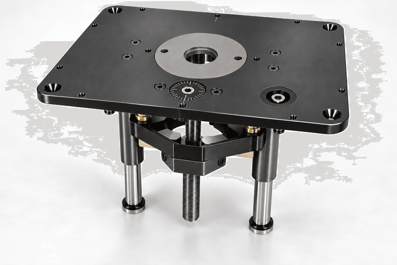
An original educational poster identifies 9 documented construction features. The numbered descriptions remain readable below the artwork on narrow screens.
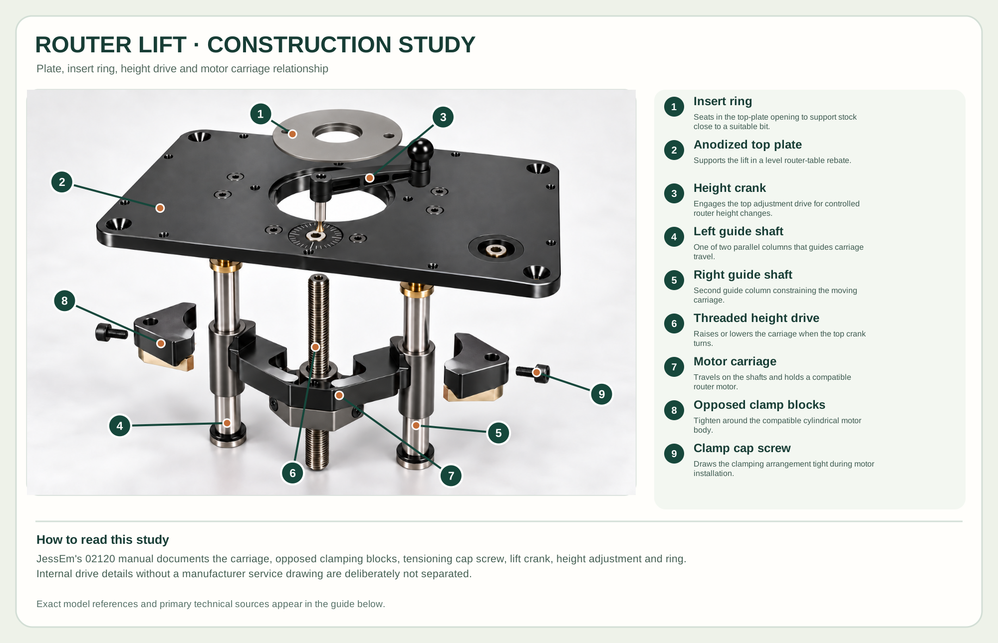
Seats in the top-plate opening to support stock close to a suitable bit.
Supports the lift in a level router-table rebate.
Engages the top adjustment drive for controlled router height changes.
One of two parallel columns that guides carriage travel.
Second guide column constraining the moving carriage.
Raises or lowers the carriage when the top crank turns.
Travels on the shafts and holds a compatible router motor.
Tighten around the compatible cylindrical motor body.
Draws the clamping arrangement tight during motor installation.
Technical references: JessEm 02120/02121 official user manual, pages 1–5 · JessEm Mast-R-Lift II model 02120 product. A central threaded height drive moves the motor-clamping carriage along two guide shafts beneath the table plate. The removable insert ring seats in the bit opening; a separate crank engages the top adjustment socket. This arrangement explains visible mechanical relationships rather than a service disassembly sequence. Original educational artwork depicts documented component groups and their relationships; it is not a service sequence or a replacement for the exact model manual.
JessEm's Mast-R-Lift II model 02120 is a router-table lift with a hard-anodized top plate, above-table height crank, cam lock, removable insert rings and a carriage that clamps the router motor. The illustration omits manufacturer graphics while retaining its documented arrangement. A lift positions a compatible router; it does not supply the motor or replace safe table and fence setup.
A height screw moves the clamping carriage along two guide shafts beneath the insert plate. Turning the supplied crank at the top adjustment socket raises or lowers the router; a separate cam lock secures the chosen height. The two opposing clamping blocks tighten around a compatible cylindrical motor body. The ring closes unused space around a bit, and the plate is leveled in the table opening. The separated study is an educational arrangement of visible documented groups, not a service or motor-installation sequence.
The plate supports the lift at the table opening. Match the removable ring opening to the bit and seat it fully before running.
A top crank drives the central threaded lift mechanism; the model manual states one full turn changes height by 1/16 inch.
Two parallel shafts guide the moving carriage and keep the motor aligned below the plate.
Opposed blocks tighten around a compatible motor. The cam lock holds a height setting; neither substitutes for checking the bit and motor clearance.
These decisions make the mechanism useful at the bench.
Check plate dimensions, rebate support, level and secure fit against the specific table before installing a motor.
Unplug the router and follow the maker's orientation and clamping instructions; keep controls accessible and the motor clear of the plate.
Use the crank in small increments, measure the actual projection, then engage the cam lock and recheck on scrap.
Record bit and height settings and verify with a scrap cut before machining final stock.
Use suitable fence and featherboards with a staged depth plan; the lift changes height, not feed control.
Isolate power and raise the collet only as the router and lift manuals permit for safe wrench access.
Use the steps for a first pass, then inspect the work before changing the setup.
The central threaded drive changes elevation while the two shafts constrain unwanted tilt.
The supplied blocks accommodate a documented range of motor diameters; do not improvise spacers or assume every router fits.
Its separated ring, blocks and crank explain relationships, not a prescribed disassembly path.
The 02120 uses the standard plate; the 02121 has a smaller top plate. Check your table's opening.
Use a bit-compatible ring so the opening supports work without contacting the cutter.
Confirm the actual motor body size and control access against the lift maker's current fit guidance.
Stop the tool and disconnect power before investigating a fault or changing a part.
Disconnect power; inspect chips, guide shafts, clamp tension and motor alignment using the maker's adjustment procedure.
Inspect cam lock engagement and the clamping carriage before making another cut.
Reset table rebate supports and leveling screws, then confirm the plate is secure.
Use the exact tool manual for setup, limits and replacement parts. These lessons, documents and model pages teach relevant techniques or help compare real variations.
These maker-owned links document relevant tools and tool brands. A product brand may use another company's factory; compare the exact model before choosing parts or accessories.
Cutters, abrasives, guards, guides, dust fittings and service parts vary by tool. Check the model plate and manufacturer manual before ordering or changing a component.
Compare the Routing family →Continue through the Tools library