
Fixed circular cutter
A small single-bevel wheel is secured with a center screw. It scores the fibers; no rotating bearing is depicted or assumed.
Set a crisp, repeatable line from one edge with a fixed circular cutter and a fine-adjustable sliding rod.
An original educational poster identifies 7 documented construction features. The numbered descriptions remain readable below the artwork on narrow screens.
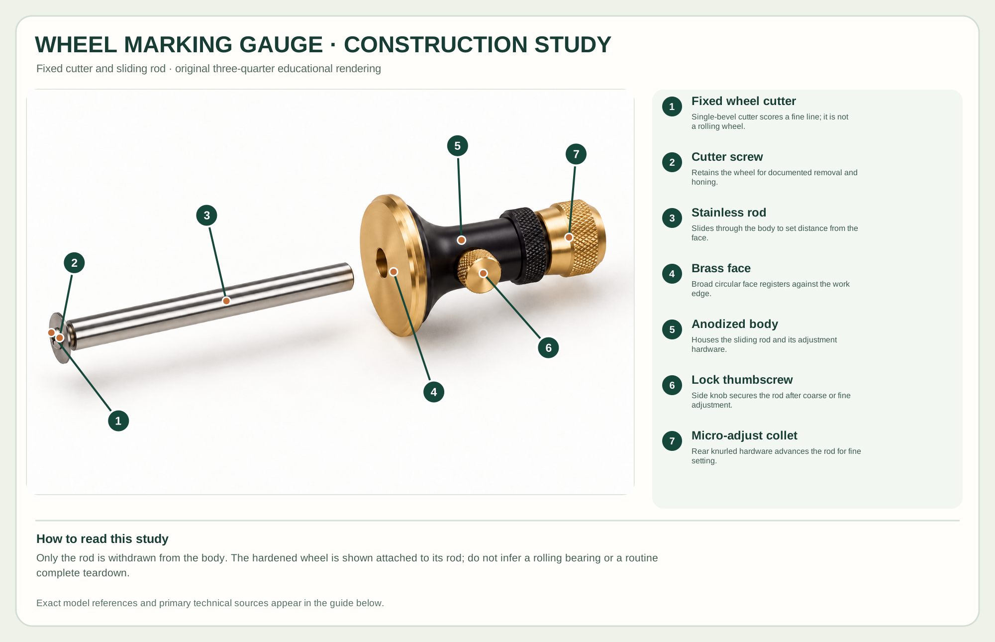
Single-bevel cutter scores a fine line; it is not a rolling wheel.
Retains the wheel for documented removal and honing.
Slides through the body to set distance from the face.
Broad circular face registers against the work edge.
Houses the sliding rod and its adjustment hardware.
Side knob secures the rod after coarse or fine adjustment.
Rear knurled hardware advances the rod for fine setting.
Technical references: Veritas 05N3510 official product · Veritas wheel marking gauge instructions. The rod withdraws for coarse setting and the wheel is fixed by a central screw. The cutter scores rather than rolling; the body, face and micro-adjust hardware remain together in this educational arrangement. Original educational artwork depicts documented component groups and their relationships; it is not a service sequence or a replacement for the exact model manual.
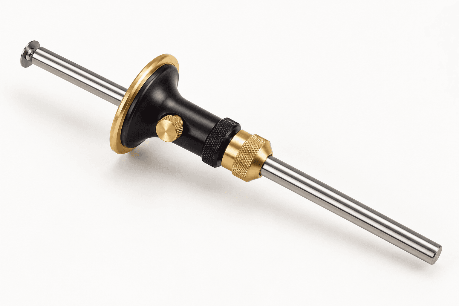
The Veritas 05N3510 micro-adjust gauge has an anodized aluminum body, a broad brass face, a sliding stainless rod and a single-bevel hardened steel wheel cutter fixed at the rod end. Despite the name, this wheel does not roll along the line. It slices a fine score. A pin gauge can work with the grain but may tear across it; the sharp circular edge is useful in both directions when set and guided correctly.
Release the side thumbscrew for a coarse rod setting. The rear collet and knurled micro-adjust hardware advance the rod in small increments, then the side screw locks it. Keep the brass face against one straight reference edge and draw the fixed cutter through a controlled pass. The central cutter screw permits the maker-documented removal for honing; the construction view retains it on the rod.
A small single-bevel wheel is secured with a center screw. It scores the fibers; no rotating bearing is depicted or assumed.
The rod slides through the body and sets the cutter's offset from the brass face.
The broad face bears against the work edge while the body guides the rod and carries the lock.
The side thumbscrew locks the rod. The rear knurled collet and brass nut provide fine setting after a coarse slide.
These decisions make the mechanism useful at the bench.
Prepare a straight edge; keep the brass face fully against it throughout the mark.
Slide close to dimension, use the micro adjust for the last correction, then lock the rod without shifting it.
Make a light first pass, then deepen only if needed. Guide with the grain direction and supported fingers.
Scribe a tenon shoulder or rebate line at a repeatable distance from an edge.
Use a known board or measured setting to transfer stock thickness to mating components.
A sharp wheel can cut a cleaner cross-grain line than a blunt pin when pressure is restrained.
Use the steps for a first pass, then inspect the work before changing the setup.
Its circular profile and bevel aid clean scoring; the wheel does not spin as the gauge travels.
Use the same reference edge for mating joinery to prevent small stock-width differences from becoming misaligned shoulders.
Pressing hard may pull the face away from the edge or follow grain; a light first pass is more reliable.
A plain gauge relies on sliding alone; this reference adds a fine-setting rear collet.
Mortise gauges can mark two parallel lines; the illustrated 05N3510 has one cutter.
Other cutter geometries need different pressure and grain handling.
Secure the work, protect sharp edges and release any stored clamping pressure before adjustment or maintenance.
Check the reference edge, face pressure, rod lock and first-pass force.
Inspect the bevel and sharpness; make a lighter pass and check grain direction.
Clean the rod, lock and fine-adjust hardware and retighten as instructed.
Use the exact model documentation for setup, limits and replacement parts. These lessons, documents and model pages teach relevant techniques or help compare real variations.
These maker-owned links document relevant tools and tool brands. A product brand may use another company's factory; compare the exact model before choosing parts or accessories.
Handles, irons, saw plates, clamping pads and other replacements vary by maker and model. Use the maker's documentation before changing a component.
Compare the Marking Tools family →Continue through the Tools library