
Adjustable 3D Push Block
Guide stock with adjustable downward, forward and lateral pressure while keeping hands on a raised handle.
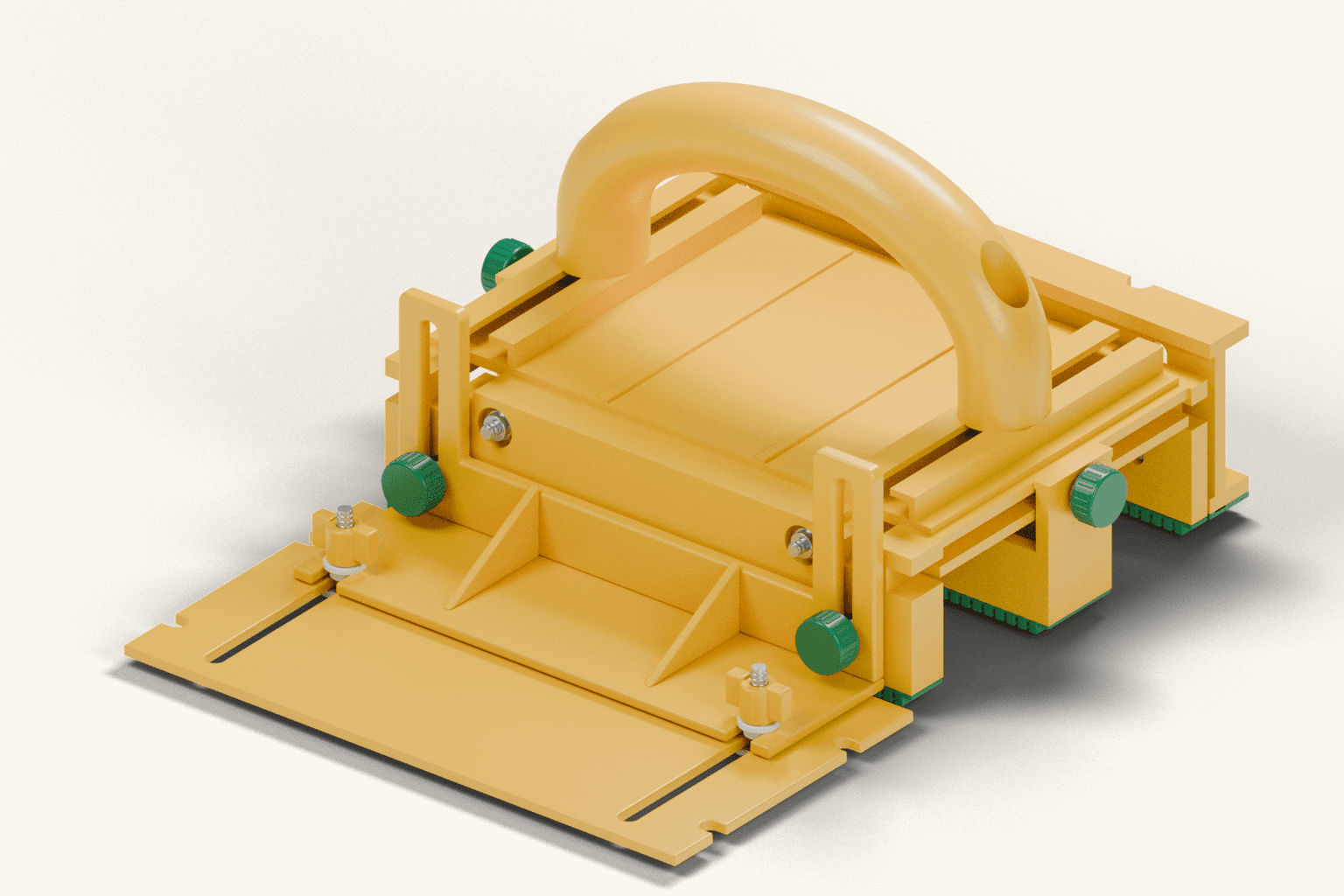
See the assembled tool and its components
An original educational poster identifies 10 documented construction features. The numbered descriptions remain readable below the artwork on narrow screens.
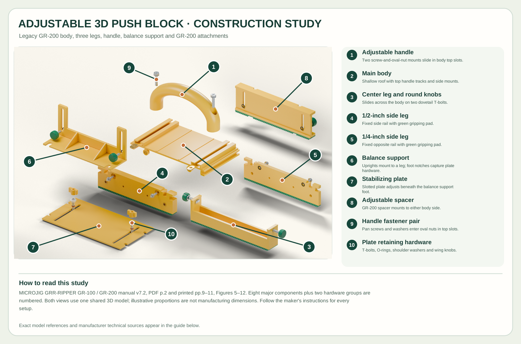
- Adjustable handle
Two screw-and-oval-nut mounts slide in body top slots.
- Main body
Shallow roof with top handle tracks and side mounts.
- Center leg and round knobs
Slides across the body on two dovetail T-bolts.
- 1/2-inch side leg
Fixed side rail with green gripping pad.
- 1/4-inch side leg
Fixed opposite rail with green gripping pad.
- Balance support
Uprights mount to a leg; foot notches capture plate hardware.
- Stabilizing plate
Slotted plate adjusts beneath the balance support foot.
- Adjustable spacer
GR-200 spacer mounts to either body side.
- Handle fastener pair
Pan screws and washers enter oval nuts in top slots.
- Plate retaining hardware
T-bolts, O-rings, shoulder washers and wing knobs.
Technical references: MICROJIG GRR-RIPPER GR-100 / GR-200 manual v7.2 · MICROJIG official user manuals · MICROJIG GR-200 video archive. The main body carries an adjustable two-point handle. Two side legs secure to opposite sides, while the center leg slides across the underside on dovetail T-bolts. The balance support mounts to a side leg through its upright slots; the stabilizing plate's shoulder-washer hardware snaps into the open notches of the horizontal foot. The adjustable spacer fastens to either body side. This is an educational component arrangement, not a service sequence. Original educational artwork depicts documented component groups and their relationships; it is not a service sequence or a replacement for the exact model manual.
What it is and what each part does
The reference is the legacy GRR-RIPPER Advanced GR-200 described in MICROJIG's GR-100 / GR-200 Instruction Manual v7.2. It has a yellow main body, an adjustable top handle, a sliding center leg and fixed 1/4-inch and 1/2-inch side legs with green gripping pads. The GR-200 package also includes a balance support, stabilizing plate and adjustable spacer. Those last two were optional upgrade parts for a GR-100, but are included in the GR-200. The illustrated hardware follows the manual's red-bag and blue-bag assembly, not newer GRR-RIPPER AIR, GRR-RIPPER+ or aftermarket accessories.
Three underside legs straddle or register the work while the center leg slides side to side in the body's end slots to establish a safe tunnel around the cutter. The two side legs are secured on opposite long sides with pan screws, washers and black O-rings. The handle changes position and angle in the body's upper slots. The balance support mounts to either side leg; the stabilizing plate's shoulder washers snap into the open notches in its horizontal foot and the plate locks with T-bolts, orange O-rings, nylon shoulder washers and yellow wing knobs. The adjustable spacer fastens to either side of the body at brass inserts. Each element changes the work contact or hand position; none is a substitute for a properly set machine.
Main body and handle
The bridge carries two top handle slots and the underside leg tracks. Two pan screws, washers and oval nuts retain the adjustable handle.
Three gripping legs
The center leg slides across the underside and locks with two green round knobs on dovetail T-bolts. The 1/4-inch and 1/2-inch side legs mount on opposite sides with four pan screws, washers and black O-rings.
Balance support and stabilizing plate
Two green thumb screws mount the balance support to a side leg. The GR-200 stabilizing plate seats at the two open notches in the horizontal support foot and is held by two T-bolt, orange O-ring, nylon shoulder washer and yellow wing-knob stacks.
Adjustable spacer
Two green thumb screws, washers and black O-rings fasten the spacer to either side of the body. Its pad can face down for grip or up in the manual's balancing setup.
How the main groups connect
Three legs shape the contact path
Set, guide and control the action
These decisions make the mechanism useful at the bench.
Set the center leg
With the machine stopped and unplugged, set the center leg to cover the work and leave the cutter path clear; tighten both round knobs and check the full pass.
Position the handle
Loosen both handle screws, move and angle the handle within its slots, then retighten so the hand remains over a stable contact area.
Add lateral support
Mount the balance support and GR-200 stabilizing plate as the manual shows. Set the plate against the fence or work without binding, then tighten both wing knobs.
Table saw rip cuts
Place the selected legs on stock so the push block can apply forward, downward and fenceward pressure through the whole pass while the blade remains in the leg tunnel.
Router table
Use the manual's orientation and fence setup to move stock past a guarded router bit while maintaining stable contact; check the bit path before starting.
Jointer
Use the gripping pads to guide suitable flat stock while following the jointer's own guard, feed direction, hand-placement and minimum-stock rules. Check the push block's contact and stability before starting.
Setup, technique and finish quality
Use the steps for a first pass, then inspect the work before changing the setup.
- Read the GR-100 / GR-200 v7.2 manual and the machine manual. Unplug the machine before assembling or adjusting the push block.
- Check all three green pads and the body for damage. Confirm the two side legs, sliding center leg, handle, balance support, plate and spacer are secure.
- Use at least two installed legs. Position the center leg so the blade or bit passes through the tunnel without touching any component; tighten both round knobs and rehearse the complete travel with power off.
- Set the handle and any support or spacer for firm, balanced contact. Tighten both handle screws, green thumbs and yellow wing knobs used in the setup.
- Use the proper fence, guard and other machine protections; set the cutter height and feed direction according to both manuals.
- Place all intended pads flat on supported work. For one push block, the manual suggests one hand on the handle and the other on top of the main body; feed smoothly and keep bare hands off the stock.
- Stop the machine before repositioning for another pass; inspect the first cut and adjust with power disconnected.
Three directions of control
The adjustable legs and handle let the operator coordinate downward, forward and lateral pressure. Their position must match the actual cut and stock width.
The center leg defines the tunnel
It is the movable underside leg; the side legs are fixed. Confirm that no leg, pad or accessory can meet the blade or bit through the full travel.
The support parts belong to GR-200
The stabilizing plate and adjustable spacer are included in the legacy GR-200, while an older GR-100 can gain them through a separate upgrade kit.
What changes by model or material
Shift the center leg to create the required cutter passage and place the side leg appropriate to the stock and fence clearance.
Move the balance support to either side leg and adjust the stabilizing plate to maintain controlled support beside the work.
The manual allows the adjustable spacer on either side with its pad facing down for grip or up for a balancing setup.
Choosing the tool
- Confirm the package and manual identify the legacy GR-200; GR-100, AIR, + and later product bundles can differ.
- Check that the three legs and pad widths suit the stock and cutter clearance.
- Keep the original hardware with each mounting group; do not assume newer accessory kits fit this assembly.
Useful accessories
- Machine-appropriate fence and guarding
- Square or rule for setup
- GR-200 included balance support, stabilizing plate and adjustable spacer
Consumables
- Replacement GRR-RIP gripping pads and maker-specified GR-200 hardware when worn
Care, troubleshooting and safety
Inspect gripping pads, machine guards and cutter clearance before use.
Care checklist
- Brush dust from the body slots, pads, brass inserts and fastener heads.
- Inspect the green pads for wear or loss of grip; replace damaged parts before use.
- Check all screws, round knobs, thumbs and wing knobs for secure engagement; do not overtighten plastic parts.
- Store flat and dry with the original hardware grouped by component.
Common mistakes
- Using an AIR, + or GR-200PRO parts diagram for this v7.2 GR-200 assembly.
- Leaving the sliding center leg or handle loose.
- Letting a pad or accessory cross the blade or bit path.
- Assuming the push block makes a too-small or unsupported workpiece safe.
Safety at the operation
- Use at least two installed legs, the correct guard, fence, blade or bit setup, and the machine manual's feed direction and minimum stock rules.
- Before power-on, sight through the tunnel and verify the cutter clears every push-block component through the entire pass; keep the fence parallel and the tool stable.
- Keep hands on the handle and body as directed, clear of the cutter; use eye and hearing protection.
- Stop and disconnect power for setup, adjustment or jam clearing. If the block is unstable or the cut feels unsafe, do not proceed.
- A push block can improve control but cannot eliminate kickback or replace other machine safety measures.
When the result goes wrong
Stop the machine; check work support, pad condition, center-leg placement, balance support and stabilizing-plate setting.
Unplug the machine; inspect the correct fastener stack, slot engagement and tightening of both mounting points.
Recheck fence alignment, lateral support, grip-pad contact and feed pressure with a scrap trial.
Stop; verify spacer or plate orientation, side selection, cutter clearance and fence path against the manual.
Manuals and educational resources
Use the exact model documentation for setup, limits and replacement parts. These lessons, documents and model pages teach relevant techniques or help compare real variations.
Manufacturer documentation
Learn and compare
Manufacturers & Brands
These maker-owned links document relevant tools and tool brands. A product brand may use another company's factory; compare the exact model before choosing parts or accessories.
Choose parts for the exact model
Gripping pads, support plates and adjustment hardware vary by model. Use the maker's documentation before changing a component.
Compare the Woodworking Safety Equipment family →Continue through the Tools library